


Support Information
M9328MX21ADSE User’s Manual, Rev. A
3-12 Freescale Semiconductor
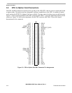
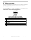
3.3 CPU to Option Card Connectors
The PK1 and PK2 connectors located at the top side of the ADS CPU card are used to connect the board
to option cards. The option cards are designed to add new capabilities to the ADS. A number of option
cards, such as the PCMCIA Adaptor Card, are available. You may want to develop your own add-on cards.
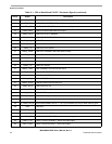
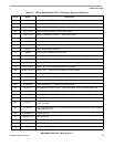
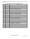
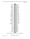
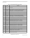
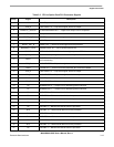
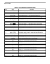
Figure 3-3 shows pin assignments for the PK1 connector and Table 3-3 provides signal descriptions for the
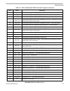
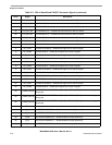
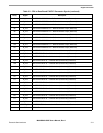
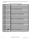
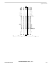
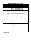
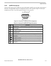
connector. Figure 3-4 shows pin assignments for the PK2 connector and Table 3-4 provides signal
descriptions for the connector.
Figure 3-3. CPU to Option Card PK1 Connector Pin Assignments
PK1
VCC 1 • • 2 CS0_B
PWMO 3 • • 4TP13
RESET_IN_B 5 • • 6 P2.5V
RESET_OUT_B 7 • • 8 NEXUSEVTI_GPIO
P2.5V 9 • • 10 SDCKE1
RW_B 11 • • 12 BCLK
CS5_B 13 • • 14 CLKO
CS3_B 15 • • 16 CS4_B
P1.8V 17 • • 18 CS1_B
A0 19 • • 20 A1
D7 21 • • 22 D8
D6 23 • • 24 D9
D5 25 • • 26 D10
D4 27 • • 28 D11
D3 29 • • 30 D12
D2 31 • • 32 D13
D1 33 • • 34 D14
D0 35 • • 36 D15
DQM1_EB1_B 37 • • 38 SDCLK
DQM0_EB0_B 39 • • 40 A18
SDCKE0 41
• • 42 A17
MA10 43 • • 44 A10
VCC 45 • • 46 A9
A16 47 • • 48 A7
A14 49 • • 50 A6
P1.8V 51 • • 52 A8
A15 53 • • 54 A11
A13 55 • • 56 P5V
A12 57 • • 58 OE_B
P5V 59 • • 60 ECB_B