


Configuration and Operation
M9328MX21ADSE User’s Manual, Rev. A
2-6 Freescale Semiconductor
the entire 64 MB address space allowed for CSD0, but the Burst Flash occupies only 32 MB of the 64 MB
space available to CS0, so it appears in two different ranges of addresses. CS1 covers 16 MB allowing
many repetitions of the memory mapped peripherals.
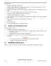
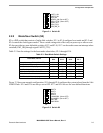
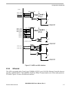
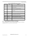
2.3.4 USB On-The-Go Interface
The i.MX21 USB OTG Device Module interfaces with a Phillips ISP1301BS USB transceiver connected
to P4, a mini AB USB connector. The interface can function as either a USB host or USB device. The
interface includes a Maxim MAX3355EUD+ USB power supply chip which can provide power on the
USB bus in host mode. This power supply chip is enabled by the USB_PWR signal. For details on the
operation of the USB interface, refer to the i.MX21 data sheet. Figure 2-6 shows the USB interface
connection.
Figure 2-6. USB OTG Interface
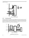
2.3.5 UART and IrDA
Figure 2-7 shows how to connect the UART and IrDA circuits.
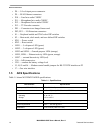
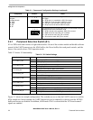
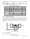
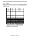
Table 2-4. M9328MX21ADSE Memory Map
Peripheral Chip Select Address Range (HEX) Act Mem Size
SDRAM CSD0
0xC000_0000 to 0xC3FF_FFFF 64 MB
Burst FLASH CS0
0xC800 0000 to 0xC9FF_FFFF 32 MB
Ethernet Controller CS1
0xCC00 0000 to 0xCC00_000F* 16 BYTES
External DUART CS1
0xCC20 0000 to 0xCC20_000F* 16 BYTES
Read CPU and
Base board versions
CS1
Read 0xCC40_0000*
D7-D0 = CPU, D15-D8 = Base board
2 BYTES
Memory Mapped I/O
CS1
Write to 0xCC80_0000* (Output) 2 BYTES
CS1
Read 0xCC80_0000* (Input) 2 BYTES
* For I/O operations only D15 - D0 are used
USB Device
D+
D-
ISP1301BS
VBUS
ID
USB MINI AB
P4
MAX3355EUD+
USB_PWR
i.MX21
SHDN
VBUS
IDIN
IDOUT