


Configuration and Operation
M9328MX21ADSE User’s Manual, Rev. A
Freescale Semiconductor 2-3
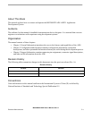
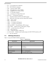
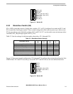
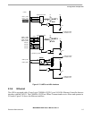
Figure 2-1. Switch S1
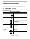
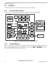
2.2.2 Mode/User Switch (S2)
S2 is a DIP switch that consists of eight slide switches. S2-1 to S2-4 configure boot mode and S2-5 and
S2-6 control the clock bypass modes. These switch settings take effect only on power up or after a reset.
S2 also provides two user definable switches (S2-7 and S2-8). S2-7 can be used to cause an interrupt when
switched (SW1_IRQ through signal UART3_CTS).
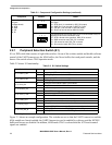
Table 2-3 lists the settings for the boot-mode subswitches, S2-1 through S2-4.
.
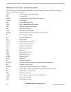
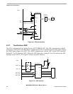
Figure 2-2 shows an example configuration. S2-1 through S2-4 configure the system to boot from the 8-bit
NAND Flash. S2-5 and S2-6 are always set to OFF. S2-7 and S2-8 are set for user-defined functions.
Figure 2-2. Switch S2
Table 2-3. Boot Mode Switch Settings
Boot Mode, Device
BOOT3
S2-4
BOOT2
S2-3
BOOT1
S2-2
BOOT0
S2-1
Internal bootstrap ROM (USB/UART) ON ON ON ON/OFF
NAND, 8-bit, 2KB per page ON ON OFF ON
NAND, 16-bit, 2KB per page ON ON OFF OFF
NAND, 16-bit, 512bytes per page ON OFF ON ON
CS0, 16-bit, D[15:0] ON OFF ON OFF
CS0, 32-bit ON OFF OFF ON
NAND 8-bit, 512bytes per page ON OFF OFF OFF
5
ON
4
8
TONE_OUT
IrDA_ON
UART1_ON
S1
1
2
36
7
JTAG_CTRL, (Set to OFF)
UART4_ON
NEXUS_ON, (Set to OFF)
PEN_CS_B
PEN_IRQ_B
5
ON
4
8
CLKMODE1, (Set to OFF)
BOOT2
BOOT0
S2
1
2
36
7
CLKMODE0, (Set to OFF)
BOOT1
BOOT3
SW1 IRQ
SW2 READ