


Configuration and Operation
M9328MX21ADSE User’s Manual, Rev. A
2-2 Freescale Semiconductor
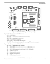
2.2.1 Peripheral Selection Switch (S1)
S1 is a DIP switch that consists of eight slide switches. Seven of the switches enable and disable software
control of the UART transceivers, the IrDA buffers, the Nexus buffer, the touch panel controls, and the
buzzer. One switch selects JTAG operation mode.
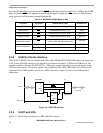
Table 2-2 shows S1 functionality.
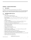
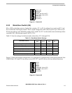
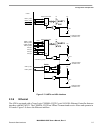
Figure 2-1 shows an example configuration. The switches are set so that the UART1 transceiver and the
IrDA module are forced enabled; the UART4 transceiver can be enabled by software; and the NEXUS
buffer and buzzer are disabled. In addition, ARM mode JTAG is selected and the LCD touch control
signals are enabled.
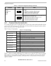
Modem Control Enable
Jumpers
(on Base board)
J3, DTR
J4, DSR
J5, CD
J6, RI
The specified RS-232 control signal of P2 connects to the specified
I/O signal.
J3 - DTR (pin 4) is controlled by SD2_D0 (output)
J4 - DSR (pin 6) can be read on SD2_D1 (input)
J5 - CD (pin 1) can be read on SD2-D2 (input)
J6 - RI (pin 9) can be read on SD2-D3 (input)
The specified RS-232 control signal of P2 is not connected to any I/O
signal and cannot be controlled or read.
J3 - DTR is forced active (positive), SD2_D0 is unused
J4 - DSR cannot be read, SD2_D1 is unused
J5 - CD cannot be read, SD2_D2 is unused
J6 - RI cannot be read, SD2_D3 is unused
Table 2-2. S1 Switch Settings
Switch Name Setting Effect
S1-1, UART1_ON
ON Forces the UART1 transceiver to be enabled.
OFF UART1_EN_B bit controls the UART1 transceiver
S1-2, UART4_ON
ON Forces the UART4 transceiver to be enabled.
OFF UART4_EN_B bit controls the UART4 transceiver
S1-3, IrDA_ON
ON Forces the IrDA module buffers to be enabled.
OFF IrDA_EN bit controls the IrDA buffers
S1-4, NEXUS_EN
ON Internal test only.
OFF Set to OFF for debugging purposes.
S1-5, JTAG _CTRL
ON Internal test only.
OFF ARM Multi-ICE mode selected after TRST.
S1-6, TONE_OUT
ON The buzzer is controlled by the PWMO output.
OFF PWMO is disconnected from the buzzer circuit.
S1-7, PEN_CS_B
ON CSPI_SS0 controls the chip enable of the Touch controller.
OFF Disables CSPI_SS0 control of the Touch controller chip enable.
S1-8, PEN_IRQ_B
ON UART3_CTS is connected to PENIRQ_B out of the Touch controller.
OFF UART3_CTS is not connected to PENIRQ_B out of the Touch controller.*
*PENIRQ_B is not connected to anything.
Table 2-1. Component Configuration Settings (continued)
Component Position Effect
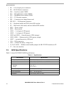
123
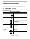
123