


Support Information
M9328MX21ADSE User’s Manual, Rev. A
3-28 Freescale Semiconductor
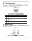
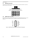
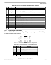
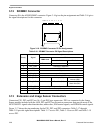
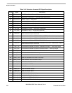
3.12 SD/MMC Connector
Connector P6 is the ADS SD/MMC connector. Figure 3-16 gives the pin assignments and Table 3-16 gives
the signal descriptions for this connector.
Figure 3-16. SD/MMC Connector P6 Pin Assignments
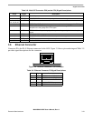
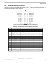
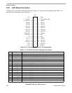
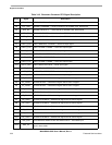
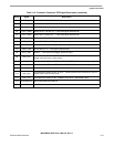
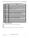
3.13 Extension and Image Sensor Connectors
Connectors PE1, PE2 and PE3 are 16 x 3-pin DIN type connectors. PE1 is a connector for the Image
Sensor module included with the ADS. PE2 and PE3 are Extension connectors that provide most of the
MC9328MX21 signals other than data bus, address bus, EIM control signals, and SDRAM control signals.
Figure 3-17 shows the pin numbering for the PE1, PE2, and PE3 connectors. Table 3-17 through
Table 3-19 provide signal descriptions. Table 3-17 covers PE1, Table 3-18 covers PE2 and Table 3-19
covers PE3.
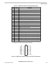
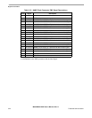
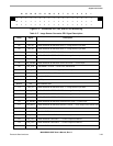
Table 3-16. SD/MMC Connector P6 Signal Descriptions
Pin(s) Signal
Description
MMC Card
SD Card
1-Bit Mode 4-Bit Mode
1 SD1_DAT3 Reserved Not Used Data Line DAT3
2 SD1_CMD Command / Response
3, 6, 11 GND GROUND
4 VCC +3 VDC power
5 SD1_CLK Clock
7 SD1_DAT0 Data Line DAT0
8 SD1_DAT1 Not Used Interrupt (IRQ) Data Line DAT1 or
Interrupt (IRQ)
9 SD1_DAT2 Not Used ReadWait (RW) Data Line DAT2 or
Read Wait (RW)
10 CSPI1_RDY Card Detect, configured as GPIO, PB20
12 SD_WP Write Protect Detect, connects to I/O input bit 0
13, 14 NC No Connection
1234567891011 13
12 14