


Support Information
M9328MX21ADSE User’s Manual, Rev. A
Freescale Semiconductor 3-21
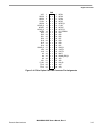
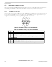
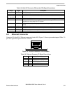
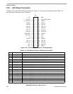
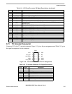
3.6 Ethernet Connector
Connector P9 is the RJ-45 Ethernet connector for the ADS. Figure 3-9 shows pin numbering and Table 3-9
provides signal descriptions for the connector.
Figure 3-9. Ethernet Connector P9 Pin Numbers
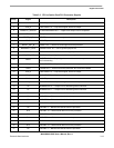
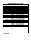
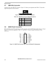
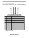
Table 3-8. Multi-ICE Connector P20 (on the CPU) Signal Descriptions
Pin(s) Signal Description
1, 2 VCC +3.0 VDC power
3 TRST_B TARGET RESET — Active low output signal that resets the target
4, 6, 8, 10, 12,
14, 16, 18, 20
GND GROUND
5 TDI TEST DATA INPUT — Serial data output line, sampled on the rising edge of the TCK signal
7 TMS TEST MODE SELECT – Output signal that sequences the target’s JTAG state machine,
sampled on the rising edge of the TCK signal
9 TCK TEST CLOCK — Output timing signal, for synchronizing test logic and control register
access
11 RTCK RETURN CLOCK
13 TDO JTAG TEST DATA OUTPUT — Serial data input from the target
15 RESET_IN_B RESET IN — Active low reset signal to the processor
17, 19 NC NO CONNECTION
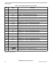
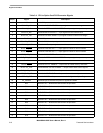
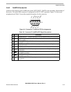
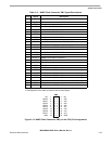
Table 3-9. Ethernet Connector P9 Signal Descriptions
Pin(s) Signal Description
1 TPO+ DIFFERENTIAL OUTPUT PLUS
2 TPO- DIFFERENTIAL OUTPUT MINUS
3 TPI+ DIFFERENTIAL INPUT PLUS
4, 5, 7, 8 NC NO CONNECTION
6 TPI- DIFFERENTIAL INPUT MINUS
1