


Configuration and Operation
M9328MX21ADSE User’s Manual, Rev. A
Freescale Semiconductor 2-15
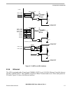
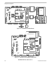
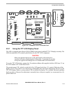
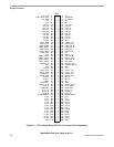
Figure 2-12. Installation of the TV Encoder Card
2.5.1 Using the TFT LCD Display Panel
The ADS is equipped with a Sharp LQ035Q7DB02 touch control enabled TFT LCD display assembly. The
ADS documentation CD contains specifications for the TFT LCD component.
CAUTION
Make sure that the input power to the main board is disconnected or
switched off before connecting the LCD module. Connecting the module
with power applied can damage the LCD module and/or the main board.
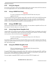
To use the TFT LCD display, connect the 34 conductor ribbon cable supplied with the ADS from J11 on
the LCD module to P7 on the Base board.
The potentiometer VR1, which is to the left of the LCD panel just below J11, controls flickering of the
display screen. This control is set at the factory and normally does not require adjustment. However, if the
TFT LCD display flickers, you may adjust VR1 to stabilize the display. Use a suitable flat head or phillips
head screwdriver. Because the adjustment is normally done with power applied, we recommend use of a
plastic blade tool.
TV ENCODER
CON
LCD CON
+5V IN
P8
F1
SW1
P9
P3 P2 P1
P4
U16
VR1
P7
P5
KEYPAD CON
P6
PE1
CSI
PE2PE3
EXP CON 2
EXP CON 1
J7
ONE WIRE
P10
P11
P12
S1
LED2
LED3
LED4
LED7
LED6 LED5
LINE IN
MIC IN
HEADPHONE
P20
PK1
PK2
J3J1 J2
CPU BOARDBASE BOARD
ON
OFF
2A
ETHERNET
EXT UART DCE UART4 DTE UART1 DCE USB OTG
BATT EM
IrDA
ACT
SD2_D0
P13
SD/MMC
UART1_ON
UART4_ON
IrDA_ON
NEXUS_EN
JTAG_CTRL
TONE_OUT
PEN_CS_B
PEN_IRQ_B
LED1
1
2
3
4
5
6
7
8
S2
BOOT0
BOOT1
BOOT2
BOOT3
CLKMODE0
CLKMODE1
SW1 IRQ
SW2 READ
1
2
3
4
5
6
7
8
LINK ACT
RESET
SW2
BUZZER
VCC PWR
STAT2
STAT1
BUS ACT
5V PWR
DTR
J3
NC
SD2_D1
DSR
J4
NC
SD2_D2
CD
J5
SD2_D3
NC
RI
J6
MULTI-ICE
U5
CPU
PX1/PY1
PX2/PY2
U6
U8
U7
U9
3
2
1
P1
P2
J1
S-VIDEO
CVBS
J3
VGA
J2
TV ENCODER CARD
PM1
PM2
NAND FLASH CARD