


Configuration and Operation
M9328MX21ADSE User’s Manual, Rev. A
Freescale Semiconductor 2-13
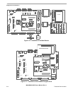
2.5 Add-On Module Connections and Usage
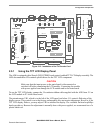
Figure 2-10 through Figure 2-12 show how to connect the ADS add-on modules. The following
paragraphs describe how to connect and use the add-on modules.
P9 Ethernet Standard Ethernet connector. A cable for direct network and one for
crossover connections (direct to a PC) have been provided.
P10 Line In Standard 3.5 mm connector for stereo audio input to the
WM8731SEDS CODEC
P11 Microphone In Standard 3.5 mm connector for a microphone. Use only dynamic
microphones with a 200 to 600 ohms impedance.
P12 Headphone Standard 3.5 mm connector for stereo audio. This is the amplified
stereo output of the WM8731SEDS. Use headphones with a 16 to 32
ohms impedance.
P13 TV encoder This connector is used with P7 together to connect the TV encoder
card.
PE1 Image Sensor Connect the image-sensor daughter board to this connector.
PE2, PE3 Expansion Standard 48 pin, three row, male DIN connectors. Can be connected
to directly or cabled to a custom circuit board.
PY1, PY2 CPU Connect the CPU module to these connectors.
PX1, PX2 Base board Connect these to the Base board PY connectors.
PK1, PK2 Option Cards Connect an appropriate Option Card to these connectors
P20 (CPU) Multi-ICE Standard ARM Multi-ICE connector
PM1, PM2
(CPU)
NAND Flash Plug the NAND Flash module into this connector.
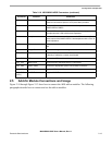
Table 2-10. M9328MX21ADSE Connectors (continued)
Connector Function Comments