


INTERFACE INFORMATION
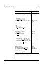
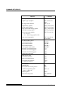
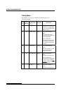
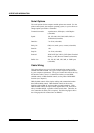
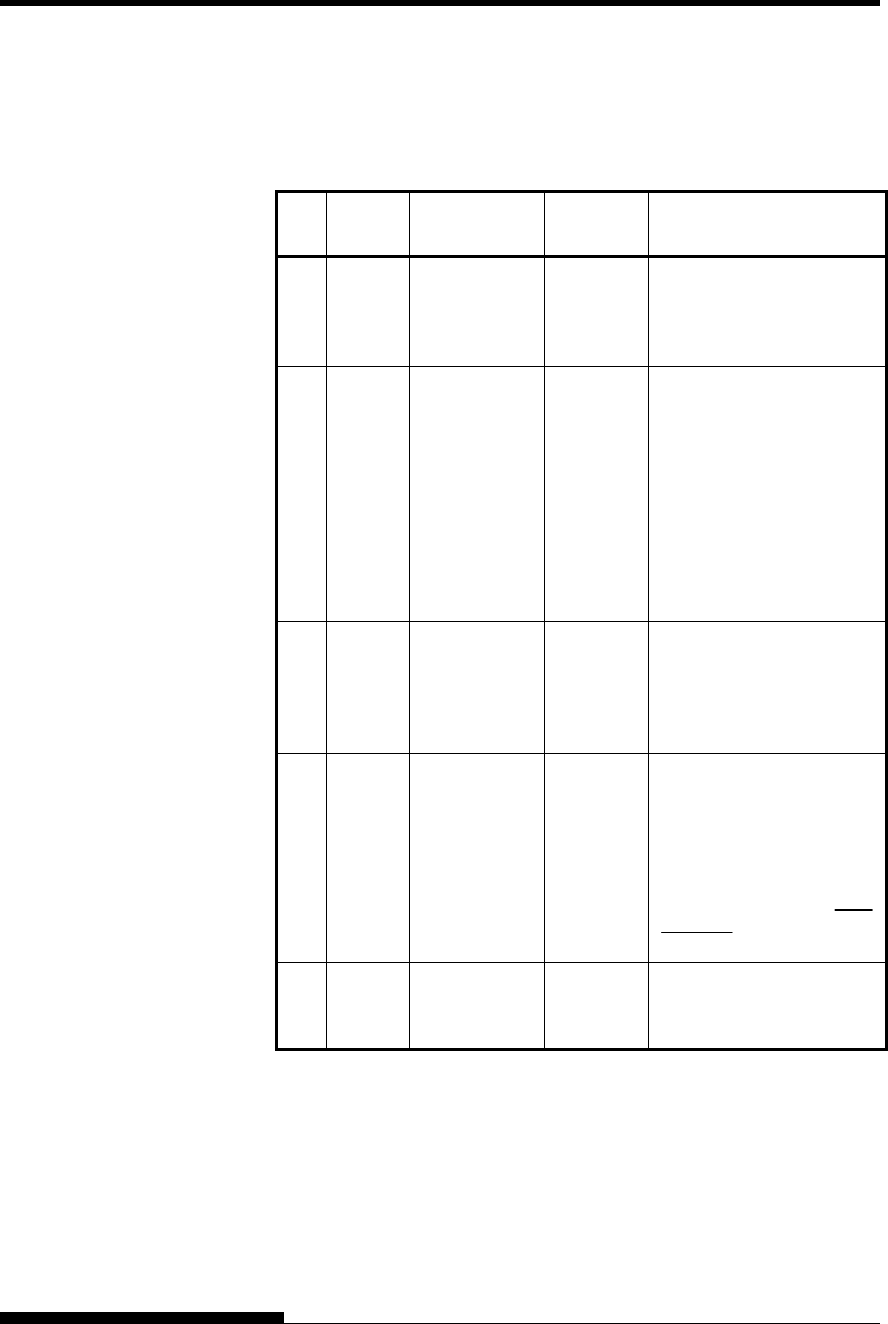
Nibble Mode
Pin numbers 2 to 9, 15 to 31, and 33 to 35 are the same as the
conventional mode.
Pin
No.
Return
Pin No.
Signal Name Direction Description
1 19 Host Clock Input
This signal is set high
when the host requests the
reverse data transfer phase
(nibble mode).
10 28 Printer Clock Output
Reverse data transfer
phase:
This signal goes high
when data being sent to the
host is established.
Reverse idle phase:
This signal is set low then
goes high to interrupt the
host, indicating that data is
available.
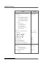
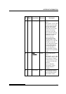
11 29 Printer Busy Output
Reverse data transfer
phase:
Data bit 3, data bit 7, then
forward path (host to
printer) busy status
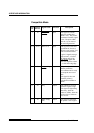
12 30 Ack Data Req Output
Reverse data transfer
phase:
Data bit 2, then data bit 6
Reverse idle phase:
This signal is set high until
the host requests data and,
after that, follows the Data
Available signal.
13
−
X Flag Output
Reverse data transfer
phase:
Data bit 1, then data bit 5
D-4 User's Manual