


CHAPTER 5: Upgrading Your Computer
80
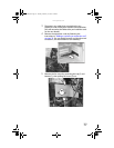
16 Install the processor onto the new system board making
sure that Pin 1 on the processor (indicated by the
silk-screened arrow on the corner of the processor)
aligns with Pin 1 on the processor socket (indicated by
the absence of a pin hole in the processor socket), then
return the lever to its locked position.
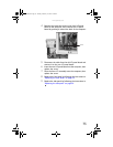
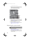
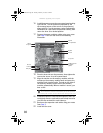
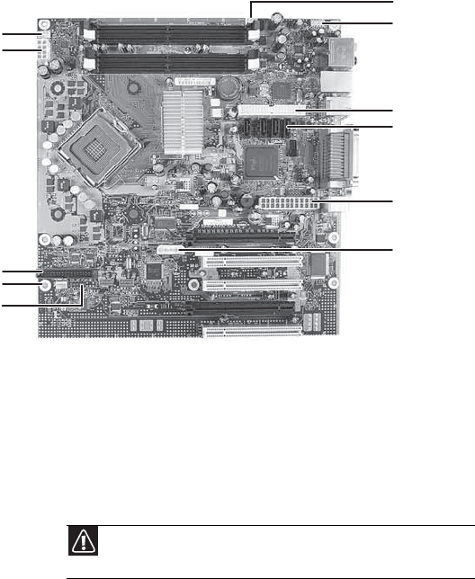
17 Connect the power and data cables using your notes
from Step 9. You can also refer to the following
illustration:
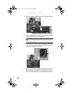
18 Place the heat sink over the processor, then tighten the
screws that secure it to the system board.
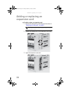
19 Align the notches on the memory modules with the
notches on the memory module banks and press the
modules firmly into the banks. The tabs on the sides of
the memory modules should secure the memory
modules automatically. When a module is secure, you
hear a click.
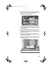
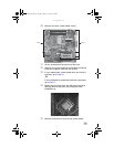
20 Install the expansion cards into the expansion slots. You
can slightly seesaw a card end-to-end to help insert the
card, but do not bend the card sideways.
21 Reconnect the expansion card cables using your notes
from Step 3.
22 Install the fan cover.
Caution
Do not touch the contacts on the bottom part of the expansion
card. Touching the contacts can cause electrostatic damage to the card.
Rear fan
Front panel audio
IDE data
Intrusion
2×12 power
Auxiliary power for
PCI Express
graphics
CPU fan
12V power
Not used
Front fan
Front panel
8512162.book Page 80 Tuesday, February 13, 2007 3:44 PM