


10 - 6
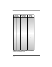
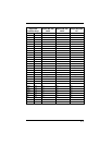
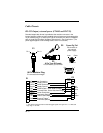
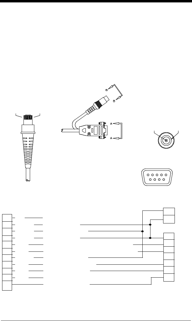
Cable Pinouts
RS-232 Output, external power (IT4410 and IT4710)
Decoded output data format is provided at the modular connector in the
Imager.Interface cables normally supplied with the Imager are terminated with a
10 pin modular plug (P1) and a 9 pin Type D connector (P3) that is compatible
with all Hand Held Products’ decoders and terminals. See chart below. (The
power pigtail applies to serial wedge cable, which is not shown.)
P1
Pin 1 Pin 10
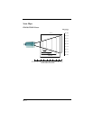
P3
9 Pin Type D Female
P3 connects to your terminal.
6
9
15
View A-A
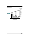
P2
Power Pig Tail
P2 connects to
the external
power supply.
Inner Outer
View B-B
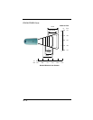
10 Pin Modular Plug
P1 connects to the Imager.
Inner
Outer
P2
|
0
5
3
2
8
7
SH
Red
Black
Green
Blue
Brown
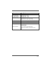
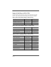
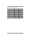
1 NC No Connection
2 Ground Supply Ground
3 +5VDC Power Connection
4 Ground Supply Ground
5 RXD Receive Data - Serial Data to Imager
6 TXD Transmit Data - Serial Data from Imager
7 +5VDC Power Connection
8 RTS Request to Send Data
9 CTS Clear to Send Data
10 TRIG External Trigger
1
SH Drain Wire (Shield)
1. The voltage requirements for external trigger signal are Logic Low <= .3 VDC and
Logic Hig >= 1.8 VDC.
P1
P3