


Adjusting the Print Head Height 3-17
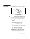
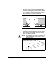
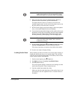
2. Use the hex wrench to turn one of the head height adjust-
ment screws counterclockwise until the end of the gauge will
not
fit under the carriage as shown in Fig. 3-8.
The access holes to the head height adjustment screws are
marked with white circles on top of the carriage.
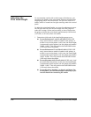
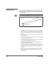
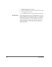
3. Turn the head height adjustment screw clockwise, until the
end of the gauge slides under the carriage and the raised
gauge step touches the carriage.
Caution
Do not allow the taller surface of the gauge to slide
under the print head carriage. Damage to the car-
riage could result.
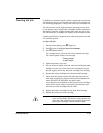
Fig. 3-8. Head height measurement points
Left (Cartridge Position 1) Right (Cartridge Position 12)
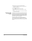
Fig. 3-9. Head height gauge
Insert the gauge to this line or this line