


22 Using McDATA Web Server
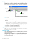
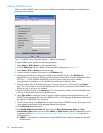
Selecting switches and links
Selected switch icons are highlighted in light blue. Selected ISLs are displayed as a heavier line. You can
select switches and links in the following ways:
• Click the icon or link to select a switch or a link.
• Press and hold Control, and select multiple switches or links.
• Right-click anywhere in the graphic window background to select all switches or links. Select Select >
All Switches, or select Select > Select All Links from the popup menu.
• Press and hold Control, and select the item again to cancel a selection. Click in the graphic window
background to cancel all selections.
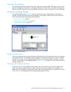
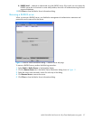
Arranging switches in the display
You can arrange individual switch icons in the topology display or allow McDATA Web Server to arrange
all switch icons for you:
• Click and drag the icon to another location in the graphic window to move an individual switch icon.
Links stretch or contract to remain connected.
• Select View > Layout Topology to arrange all switch icons in the topology display automatically.
By default, the Toggle Auto Layout box in the View menu is checked which causes McDATA Web Server to
arrange the icons when you select Layout Topology.
You can save a custom arrangement, or layout, and restore that layout during a McDATA Web Server
session. Begin by arranging the icons, then select View > Remember Layout. Un-select Toggle Auto Layout
> Layout Topology to restore the saved layout.
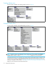
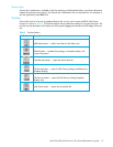
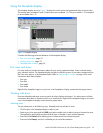
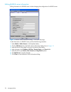
Opening the faceplate and topology display popup menus
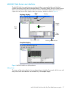
The topology display shows all switches that are able to communicate and all connections between
switches. The faceplate display shows the front of a single switch and its ports. Menu options vary with
each type of popup menu.
• Right-click the graphic window background to open the fabric popup menu in the topology display.
• Right-click the switch icon in the graphic window to open the switch popup menu in the topology
display.
• Right-click the link to open the link popup menu in the topology display.
• Right-click the faceplate in the graphic window to open the switch popup menu in the faceplate display.
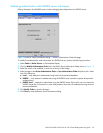
Topology data windows
The topology display provides the following data windows corresponding to the data window tabs:
• Devices – displays information about devices (hosts and storage targets) connected to the switch. Refer
to ”Devices data window” on page 68 for more information.
• Active Zoneset – displays the active zone set for the fabric including zones and their member ports.
Refer to ”Active Zone Set data window” on page 47 for more information about this data window.
Refer to ”Zoning a fabric” on page 50 for information about zone sets and zones.
• Switch – displays current network and switch configuration data for the selected switches. Refer to
”Switch data window” on page 68 for more information.
• Link – displays information about the inter-switch links. Refer to ”Link data window” on page 47 to for
more information.