


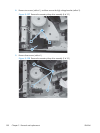
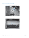
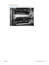
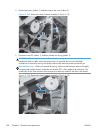
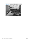
4. Remove one screw (callout 1), and then remove the cover (callout 2).
Figure 2-169 Remove the laser/scanner assembly (Y/M) (4 of 12)
2
1
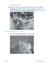
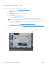
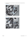
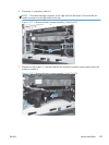
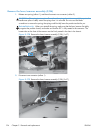
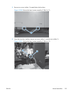
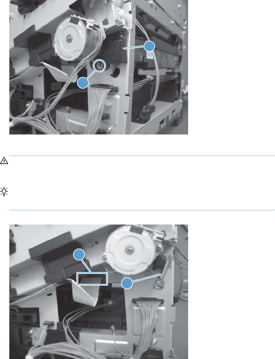
5. Disconnect one FFC (callout 1), and then release one spring (callout 2).
CAUTION: The spring is not captive. Do not lose the spring when it is removed. Use a pair of
needle-nose pliers to safely retain the spring when it is removed. Do not use a flat blade
screwdriver to remove the spring; the spring could forcibly leave the product and strike you.
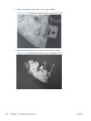
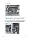
Reinstallation tip When you reinstall the spring, make sure that the laser/scanner fits tightly
up against the product chassis, and make sure that the FFC is fully seated in the connector. The
locator tabs on the front and rear of the scanner must be firmly seated in the slots in the chassis.
Figure 2-170 Remove the laser/scanner assembly (Y/M) (5 of 12)
2
1
188 Chapter 2 Removal and replacement ENWW