


Removal and Installation
8-34
HP DesignJets 500, 510 and 800 Series Printers Service Manual
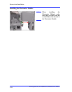
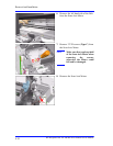
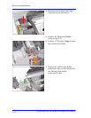
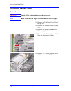
4. Disconnect the Trailing Cable and
unclip the Ferrite and remove.
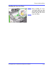
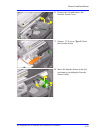
5. Remove the Electronics Module -
Refer to Page 8-24.
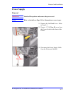
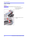
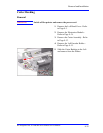
6. Remove 2 T-20 screws (Type A) from
the Left Encoder Holder.
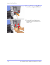
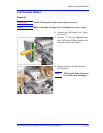
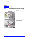
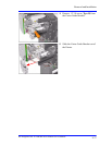
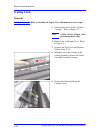
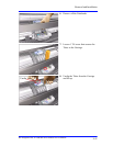
7. Remove the Left Encoder Holder,
making sure that you first unclip both
the Trailing Cable and the
Interconnect Cable.