


34
Chapter 2, Making Measurements
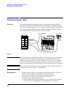
Code Domain Phase
Code Domain Phase
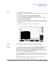
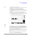
Overview Similar to the Code Domain Power measurement, this measurement shows the
relative phase relationship of the various Walsh channels referenced to the pilot
channel (Walsh 0).
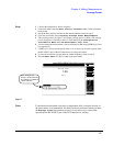
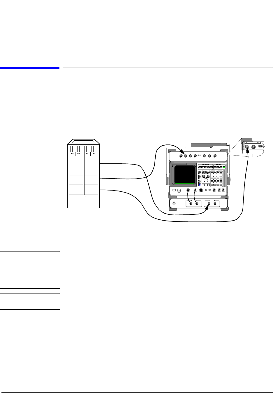
Figure 14
CAUTION: Before performing any transmitter measurements, make sure that the power level applied
to the RF IN/OUT port of the PCS Interface does not exceed the published limit. For
CDMA base station signals this is 1 Watt (+30 dBm). You may have to use an external
attenuator or directional coupler, depending on the power output for your transmitter.
Signal levels greater than the specified maximum can cause damage to the test equipment.
NOTE: The test procedures outlined in this section require that you have already configured the
Test System as outlined in chapter 1, "Getting Started".
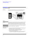
Requirements • You must have a means of turning on the base station transmitter and bringing up
various Walsh channels (such as Pilot, Sync, Traffic, and Paging).
• Synchronization is required, so you must have an Even-Second clock signal and a
reference timebase (typically 19.6608 MHz) from the base station.
• You must know the following about the base station and setup:
❒ The base station channel number setting.
❒ The PN Offset for the base-station-under-test. If you do not know the PN Offset,
determine it by selecting Search for PN Offset in the main menu.
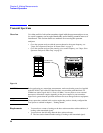
H
H
RF IN/OUT
SYNTH
REF IN
(Rear Panel)
EVEN SECOND/
SYNC IN
Time Base
Transmitter Port
Even-second
Clock