


38
Chapter 2, Making Measurements
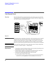
Transmit Spectrum
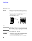
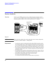
Steps: Go to
Spectrum Analyzer
& Enter Freq
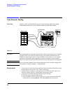
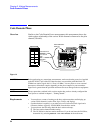
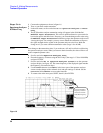
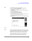
1 Connect the equipment as shown in figure 16.
2 Turn on your base station transmitter.
3 In the main menu, scroll to and select Go to Spectrum Analyzer & Enter
Freq.
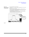
4 The PCS Interface analyzer attenuation setting will appear in the field labelled
HP83236 Input Attenuator. This value is optimized based on your entries for
base station power and cable losses. However, you can make changes to the value using
the HP83236 Input Attenuator field before going to the spectrum analyzer and
viewing the signal. For example, you may want to reduce the attenuation to improve
the signal strength relative to that of the spectrum analyzer noise floor. Make the
change now if you want a different attenuation value (range is 0 to 40 dB).
NOTE: Your change to the attenuation value, if you make one, will only be effective while using
the spectrum analyzer screen. When you return to the main menu, the value will be re-set
to the computed optimum value.
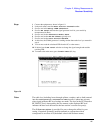
5 Scroll to and select Spectrum Analyzer Freq.
6 Enter the frequency of interest using the DATA keys (the range is 1710 to 1990 MHz)
and press ENTER.
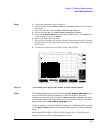
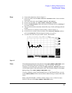
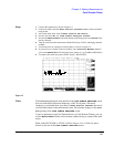
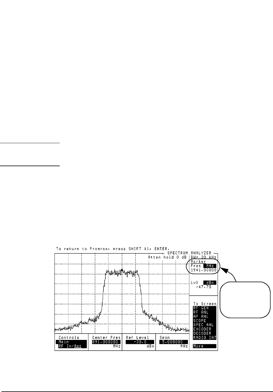
7 Scroll to and select Go to Spectrum Analyzer Screen to see the spectrum
analyzer display (see figure 18). The center frequency of the displayed signal matches
the frequency you entered in step 6.
8 Use the Controls area (set to Main) in the lower part of the spectrum analyzer
screen to make changes to the reference level and span settings as desired. Set the
Controls field to Marker to use marker functions.
9 To return to the main menu press SHIFT, then k1, then ENTER.
Figure 18
Note that the Marker
Frequency readout is
corrected to read the
actual PCS frequency.