


58
Chapter 3, Operating Overview
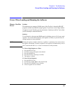
Viewing Instrument Connections
Viewing Instrument Connections
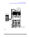
In setting up your Test System, you may have questions about connections
between the Test Set, Cellular Adapter, and PCS Interface as well as the
connections to the CDMA/PCS base station. In the Configuration
Information Menu
is a selection that displays connection diagrams for the
front and rear panels.
Steps 1 From the main menu, select Configuration Information Menu.
2 Make sure that you have your desired entries in the fields of the Configuration
Information Menu (see Notes, below).
3 Scroll to and select Connection Drawing Menu.
4 For a diagram of front panel connections, scroll to and select Show Instrument
Front Panel Connections.
5 For rear panel connections, scroll to and select Show Instrument Rear Panel
Connections.
6 You can exit the connection diagram screen by pressing the Continue (k2) key.
7 Press the Prev Menu (k5) key to return to the Configuration Information
Menu.
8 Press the Main Menu (k5) key to return to the main menu level.
Notes The connection diagrams change as a function of the entries into the
Configuration Information Menu. For this reason, make sure you have
entered your desired values before viewing the instrument connections.
Connection diagrams for each CDMA test are also shown in chapter 2, "Making
Measurements".