


Contents-2
HP 8517B S-Parameter Test Set Manual
2. Installation
InitialInspection ........................................... 2-2
OperatingEnvironment................................... 2-2
StoringtheTestSet ...................................... 2-2
AccessoriesSupplied .................................... 2-2
Figure 2-1. Accessories Supplied with the HP 8517B Test Set .... 2-3
Table 2-1. Accessories in Figure 2-1 ........................ 2-3
InstallingtheTestSetIntoaSystemRack ....................... 2-4
InstallingtheTestSetonaBench........................... 2-4
Figure 2-2. Recommended Static-Free Workstation Configuration .2-4
ConfiguringtheTestSetinaSystem ........................... 2-5
Figure 2-3. Configuring an HP 8517B Test Set in a System ...... 2-5
ConnectingtheSystemCables ............................. 2-6
Table 2-2. Connection Instructions and Connector Descriptions .. 2-6
ConnectSystemPower................................ 2-6
andControlCables ................................... 2-6
Signal Path Connections . .............................. 2-6
TestPortConnectors.................................. 2-6
Anti-RotationClamp.................................. 2-6
ReplacingO-RingsinAnti-RotationClamps .................. 2-6
PackagingtheTestSet....................................... 2-7
3. Operating the HP 8517B Test Set
Front-PanelFeatures ........................................ 3-1
Figure 3-1. Front-Panel Features of the HP 8517B Test Set ...... 3-1
Table 3-1. Front-Panel Description ......................... 3-1
Rear-PanelFeatures......................................... 3-2
Figure 3-2. Rear-Panel Features of the HP 8517B Test Set ....... 3-2
Table 3-2. Rear-Panel Descriptions ......................... 3-2
ControllingMultipleTestSets ................................ 3-3
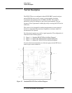
Figure 3-3. RF and IF Switching with Two Test Sets ............ 3-4
Table 3-3. RF and IF Switch Settings in Figure 3-3, Above ....... 3-4
Multiple Test-Set Connections . . .............................. 3-5
InitializationatPower-Up................................. 3-5
SelectingaTestSet ...................................... 3-5
Table 3-4. Selecting a Test Set When Multiple Units are Configured 3-6
TestSetIFSwitching ................................. 3-6
TestSetAddressing................................... 3-6
RFSwitchDriverControl.............................. 3-6
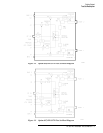
Figure3-4. RFandIFSwitchingwithFourTestSets........ 3-7
Table 3-5. Coaxial Switch Settings for Figure 3-4, Above ........ 3-7
MeasurementCalibration .................................... 3-8
MeasuringHigh-PowerDeviceswithOption004 ................. 3-9
ChangingSignalPathStatesAfterSystemCalibration............. 3-10
ChangingtheTestPortAttenuators ........................ 3-10
StoringTraceMemories ................................. 3-11
ViewingNormalizedParameters........................... 3-11