


HP 8517B S-Parameter Test Set Manual
5-3
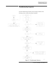
Troubleshooting the Test Set
Theory of Operation
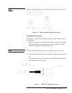
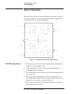
The Reference Signal
Path
• The reference signal is routed from the switch/splitter through the
20-7 dB tapered pad (AT1) to attenuate any VTO feed-through signals.
• The signal is then applied to A10, the a1 sampler assembly, where it is
down-converted to a 20 MHz IF (intermediate frequency).
• Because the RF power is being routed to Port 1, the a1 IF signal is used
to phase lock the network analyzer. Had the RF power been routed to
Port2,thea2IFsignalwouldhavebeenusedtophaselockthenetwork
analyzer.
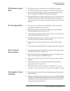
The Test Signal Path • The test signal is routed from the switch/splitter (A18) to the 60 dB
programmable attenuator (A16) for Port 1.
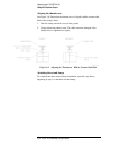
• The signal may then be attenuated in 10 dB steps or passed through
without attenuation to Port 1 bias tee (A7).
• A bias supply to provide dc voltage to Port 1 bias tee can be connected
to J8 on the rear panel of the test set, also.
• The RF signal rides this dc level which is used to turn active devices on
(bias ON) so their S-parameters can be measured.
• Beyond the bias tee, the test signal travels to the directional coupler
(A6).
• At the coupler, the incident RF power is applied to the device under test.
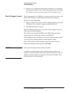
The S
11
and S
21
Measurements
• The signal reflected from the DUT is separated from the signal incident
to the DUT by the Port 1 coupler (A6).
• The reflected signal exits the coupler and is applied to b1 sampler (A12),
then is down-converted to a 20 MHz IF signal.
• The S
11
measurement is the ratio of the two IF signals from a1 and b1
samplers.
• The incident signal is transmitted through the DUT, through Port 2
coupler, then into b2 sampler (A13).
• The incident signal is down-converted to a 20 MHz IF so S
21
can be
measured. S
21
is the ratio of the two IF signals from samplers a1 and b2.
The Sampler Control
Switching
• The samplers may be turned on and off, depending upon the parameter
being measured.
• Sampler switching is controlled by a microprocessor on the HP-IB board
assembly (A4). The default condition (test set power ON and no HP-IB
commands sent by the network analyzer) is for the test set to be active
with the RF signal applied to Port 1.