


HP 8517B S-Parameter Test Set Manual
3-2
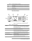
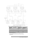
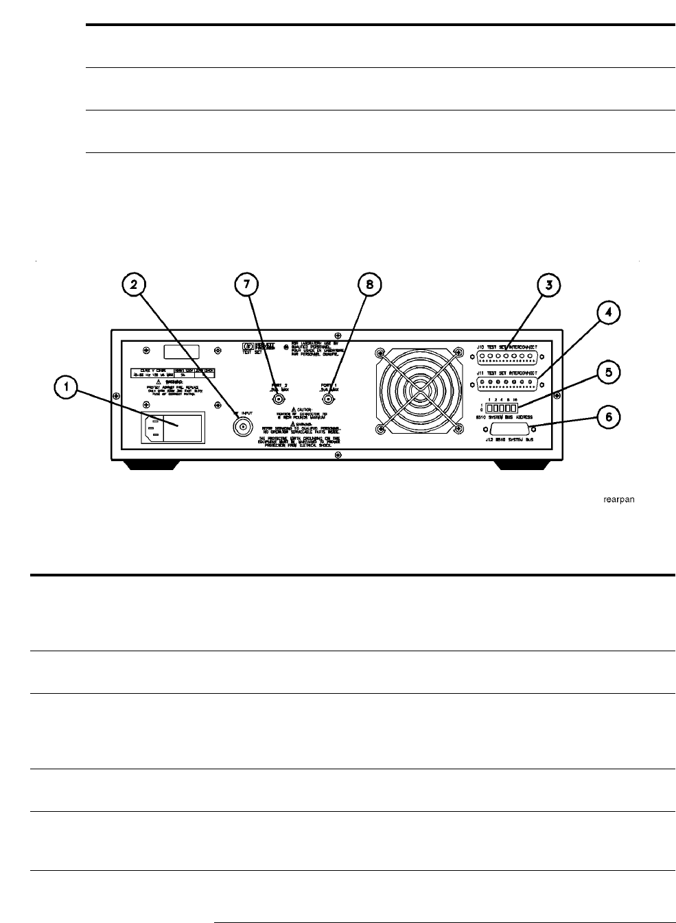
Rear-Panel Features
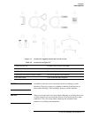
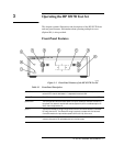
Figure 3-2 Rear-Panel Features of the HP 8517B Test Set
(6) a1 LED This LED indicates that the test set is internally switched to the S
11
or S
21
mode and source power
is switched to Port 1.
(7) a2 LED This LED indicates that the test set is internally switched to the S
22
or S
12
mode and source power
is switched to Port 2.
(8) Port 2 This test port transmits RF energy from the source to the DUT and receives reflected or transmitted
RF energy from the DUT.
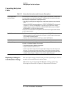
Table 3-2 Rear-Panel Descriptions
(1) Line Module Houses the line cord connector, line fuse and line voltage selector. Pull out the right side
of the line module cover to replace or change the fuse or to change the voltage selection.
Remove the voltage selector drum to rotate it to a different voltage setting. Recommended
fuse values are printed on the rear panel.
(2) RF Input A 2.4 mm connector that receives RF energy from the source. Connections made to this
input must be torqued no more than 90 N-cm (8 in-lb).
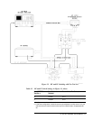
(3) J10 Test Set Interconnect Used only in test sets with Option 001. It allows connecting another test set to the option
001 test set. Up to four test sets can be serially connected to the analyzer. The HP 8510C
system automatically selects the IF output from the chosen test set for processing and
display. Refer to “Controlling Multiple Test Sets” in this chapter for more information.
(4) J11 Test Set Interconnect Transmits the IF signal from the test set to the HP 85102 IF detector. It also transmits
control signals bi-directionally.
(5) HP 8510 System Bus Address Switch A five-pole binary-weighted switch sets the test-set’s system bus address. The binary
weight of each pole is indicated on the rear panel. So are the On and Off positions. The
default setting is decimal twenty (off-off-on-off-on, from left to right).
Table 3-1 Front-Panel Description (Continued)