


HP 8517B S-Parameter Test Set Manual
6-5
HP 8517B Test Set Replacement Procedures
Assembly Replacement Procedures
Assembly Replacement Procedures
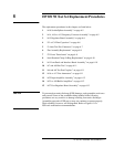
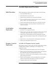
Initial Precautions Before beginning any of the procedures in this chapter, do the following:
1. Turn off the HP 8517B test set.
2. Disconnect the test set’s power cord.
3. Remove the top- and side-covers, trim strips, and handles.
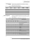
4. Do not exceed the maximum torque necessary to secure a connector.
Refer to Table 6-1 for torque specifications.
5. Exercise caution with semi-rigid cables; they can be bent very easily.
6. Reverse an assembly’s removal procedure for reinstallation, unless
otherwise instructed.
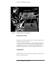
Switch/Splitter
Replacement
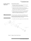
A18 Switch/Splitter Assembly
1. See Table 6-2 for component locations.
2. Remove the five semi-rigid cables and the three flexible cables from the
switch/splitter. (Reposition cables as required to ease removal.)
3. Remove the two fixed attenuators from the switch/splitter (note that
there are three fixed attenuators in Option 007, and in Option 004 “plus”
007).
4. Remove the two screws that attach the switch/splitter to the bracket.
5. Remove the switch/splitter from the test set.
Frequency Converter
Replacement
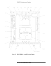
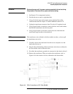
A14, A10 to A13 Frequency Converter Assembly
The frequency converter consists of the A14 VTO (voltage-tuned oscillator)
assembly and four samplers, A10 through A13. See Figure 6-2 for
component locations.
1. Remove the semi-rigid cable attached to each of the four samplers.
2. Remove the four in-line attenuators from the samplers (only in Options
007, Option 002 “plus” 007, and Option 004 “plus” 007).
3. Remove the six flexible cables from the frequency converter by pulling
gently on the gold connector.
4. Remove the four frequency converter mounting plate screws and the
bracket screw that fastens the frequency converter to the chassis.
5. Unplug the ribbon cable near the front panel.