


6-8
HP 8517B S-Parameter Test Set Manual
HP 8517B Test Set Replacement Procedures
Assembly Replacement Procedures
Fan Assembly
Replacement
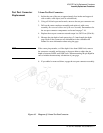
B1 Fan Assembly
Turn off the test set and disconnect the power cord from the ac-power mains.
WARNING
Electrocution can result if ac power remains connected to the test set during
this procedure. Disconnect the ac power cord before starting.
To replace the B1 fan assembly, remove T1 transformer to expose the ends of
the fan wires which must be de-soldered from the line module, FL1. Refer to
Chapter 7, “Replaceable Parts” in this manual for a detailed view of the fan
and transformer hardware.
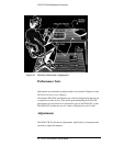
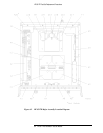
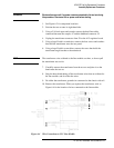
1. See Figure 6-2 for component locations.
2. Position the test set on its right-hand side.
3. Using a 5/16-inch open-end wrench, remove the hard-line cables
connected between the couplers A7 and A9 and the bulkhead connectors
J2 and J5.
4. Unplug the transformer connector at J2 on the A15 regulator board.
5. Using a large Pozidriv screwdriver, remove the four screws and washers
that hold the transformer onto the rear panel.
6. Using a large Pozidriv screwdriver, remove the screw that holds the
transformer angle bracket to the main deck.
NOTE
The transformer wires soldered to the line module are short, so do not pull
the transformer out too far.
7. Carefully remove the transformer from the test set and place it on the
bench near the test set.
8. Strip the heat shrink tubing off the two fan wires, then de-solder the
wires from the line module. Cut any cable ties restraining the fan wires.
9. Using a small Pozidriv screwdriver, remove the screw and lockwasher
that secure the green/yellow fan ground wire to the top of the rear panel
frame.
10. Using a small Pozidriv screwdriver, remove the four screws that hold the
fan to the rear panel. Remove the fan assembly.
Power Transformer
Replacement
T1 Power Transformer
Turn off the test set and disconnect the power cord from the mains.