


HP 8517B S-Parameter Test Set Manual
5-7
Troubleshooting the Test Set
Troubleshooting Procedures
Troubleshooting Procedures
The troubleshooting procedures in this chapter are listed below:
• “A15 Primary Regulator Board Assembly” on page 5-7
• “A27 Post-Regulator Board Assembly” on page 5-7
• “Self-Test Indicators” on page 5-9
• “HP 85102 IF Amplifier Test” on page 5-12
• “Unratioed Power Test” on page 5-14
• “HP 8517B, Option 007 Unratioed Power Test” on page 5-20
• “Finding the Faulty Assembly” on page 5-23
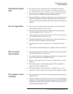
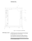
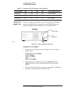
A15 Primary Regulator
Board Assembly
Use a digital voltmeter to check the voltages and an oscilloscope to check for
a maximum ripple level as listed in Table 5-2.
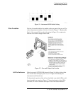
A27 Post-Regulator Board
Assembly
(Option 007, Only) Use a digital voltmeter to check the voltages and an
oscilloscope to check for a maximum ripple level as listed in Table 5-3.
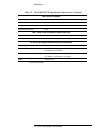
Table 5-2 Power Supply Voltages to A15
Nominal Voltage Test Point Voltage Range Maximum Ripple
Peak-to-Peak
+5.05 Vdc A15TP1 +4.75 to +5.25 2 mv
–5.20 Vdc A15TP2 –4.90 to –5.50 2 mv
+14.85 Vdc A15TP3 +14.10 to +15.60 2 mv
–14.85 Vdc A15TP6 –14.10 to –15.60 2 mv
Table 5-3 Power Supply Voltages to A27
Nominal Voltage Test Point Voltage Range Maximum Ripple
Peak-to-Peak
+5.0 Vdc A27TP1 +4.75 to +5.25 2 mv
–3.50 Vdc A27TP2 –3.26 to –3.75 2 mv