


5-14
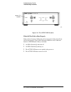
HP 8517B S-Parameter Test Set Manual
Troubleshooting the Test Set
Troubleshooting Procedures
Unratioed Power Test
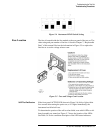
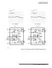
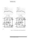
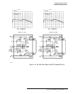
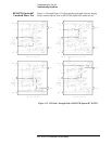
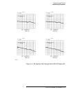
We will examine six RF signal paths in the test set by observing their
associated IF signals. Figure 5-10 through Figure 5-15 show the test set
traces (and simplified block diagrams) that are typical for RF paths 1
through 6.
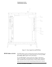
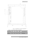
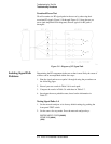
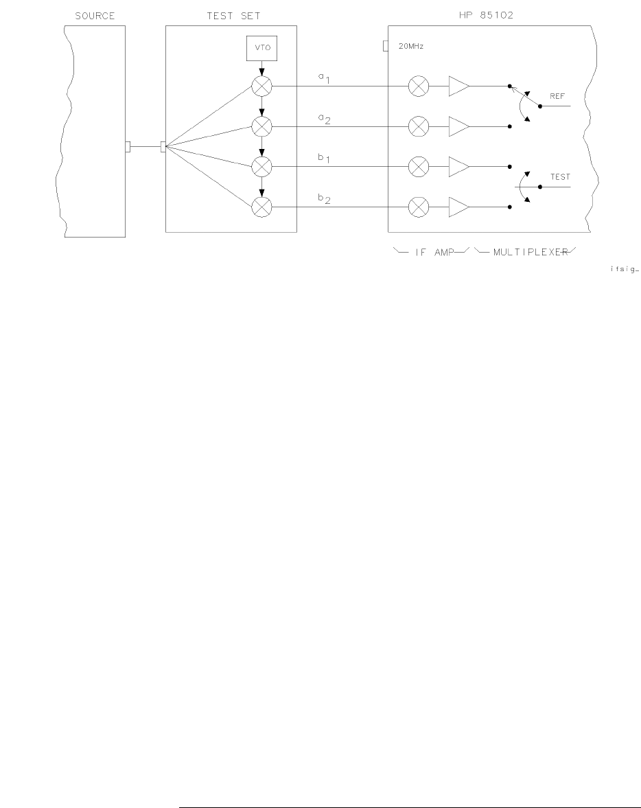
Figure 5-9 Diagram of IF Signal Path
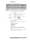
Isolating Signal Path
Problems
Determining the RF component in the test set that is most likely the cause of
a failure can be accomplished within four steps:
1. Run the signal-path tests on paths 1 through 6 using the procedures on
the following pages.
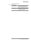
2. Record your test results in Table 5-6 for each path.
3. Compare the results in Table 5-6 with those in Table 5-7.
4. Investigate the most probable cause, based on the information in
Table 5-7.
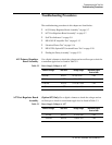
Testing Signal Paths 1-4
1. Set the network analyzer to its factory default settings by pushing the
front-panel TEST switch.
2. Set the source for step mode. Press the network analyzer keys:
INSTRUMENT STATE
[PRESET]
STIMULUS
[MENU]
{STEP}