


HP 8517B S-Parameter Test Set Manual
Contents-3
MakingOperationalChecks ..................................3-13
PerformanceVerification ....................................3-14
UsingAnti-RotationClamps .................................3-15
Attachthefirstclamp.................................3-15
Figure 3-5. Using a Torque Wrench Correctly ................3-16
Positioningthethumb-screw ...........................3-16
Figure 3-6. Visually Aligning Clamp and Nut Flats ............3-17
Positioning the connector .............................3-17
Figure 3-7. Mating the Clamp and Nut Flats .................3-17
Aligningthethumb-screw .............................3-18
Figure 3-8. Aligning the Thumbscrew With the Counter-Sink Hole 3-18
Attachingthesecondclamp............................3-18
4. Specifications
MechanicalSpecifications ....................................4-1
SupplementalCharacteristics ..................................4-1
Table 4-1. HP 8510/HP 8517B Mechanical Specifications .......4-1
Table 4-2. HP 8510/HP 8517B Supplemental Characteristics .....4-1
5. Troubleshooting the Test Set
TheoryofOperation .........................................5-2
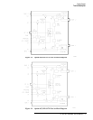
Figure 5-1. Standard HP 8517B RF Block Diagram ............5-2
TheRFSourcePower.....................................5-2
TheReferenceSignalPath .................................5-3
TheTestSignalPath......................................5-3
The S
11
and S
21
Measurements .............................5-3
TheSamplerControlSwitching.............................5-3
TheLOSignalControl....................................5-4
Troubleshooting Sequence . ...................................5-5
Figure 5-2. Troubleshooting Flowchart ......................5-5
Equipment Needed But Not Supplied . . ......................5-6
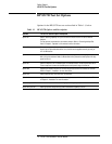
Table 5-1. Equipment Required, But Not Supplied ..............5-6
Troubleshooting Procedures ...................................5-7
Table 5-2. Power Supply Voltages to A15 .....................5-7
Table 5-3. Power Supply Voltages to A27 .....................5-7
Figure 5-3. Power Supply Fuses and Test Points ...............5-8
HP-IBAddressSwitch ....................................5-8
Figure 5-4. Instrument HP-IB Switch Setting ..................5-9
FuseLocation ...........................................5-9
Figure 5-5. Fuse and Voltage Cam Location ...................5-9
Figure 5-6. The ACTIVE LED Location .....................5-10
IftheSelf-TestFailstoRunProperly ....................5-10
Figure 5-7. HP 8518B Test Set, A4 Board Assembly LEDs .......5-11
Table 5-4. Instrument Self-Test Indicator State Definitions ......5-11
Figure 5-8. Service Adapter Connections ....................5-12
UsingtheServiceAdapter.............................5-12
ServiceAdapterConclusions...........................5-13
Table 5-5. Results Observations ...........................5-13