


HP 8517B S-Parameter Test Set Manual
3-6
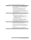
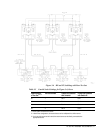
Table 3-4 Selecting a Test Set When Multiple Units are Configured
Test Set IF Switching A test set is selected via the built-in capability of the analyzer to generate an addressed
command to each test set. Each time you change the
{HP-IB ADDRESS}
{TEST SET}
function (refer to LOCAL [MENU] in the
HP 8510C Operation and Service Manual
), the
network analyzer does the following:
• switches the IF signal of the previously addressed test set to external
• switches the IF signal of the newly addressed test set to internal
• sets the test set’s front panel ACTIVE LED to indicate test-set status
• applies the active test set’s IF signals directly to J11 TEST SET INTERCONNECT
• passes the inactive test set’s IF signals at J10 through to J11 and on to the next
test set or to the network analyzer
Test Set Addressing You can change the test set address via program control, or via the network analyzer front
panel keys. You must also change the mechanical switches on the test-set’s rear panel.
Here’s how:
1. Change the test set address via the network analyzer keys;
a. On the analyzer’s front panel, press the INSTRUMENT STATE [LOCAL] key, then
press
{TEST SET}
. The test set’s address appears on the display.
b. Using the key pad, enter the desired address for the test set, then press [x1]. The new
HP-IB address appears on the display.
2. Change the test set address via the HP-IB command:
From the controller, enter the HP-IB ADDRESS; command, followed by the
address value. Refer to the command reference for programming details.
3. Reset the mechanical switches on the test-set’s rear panel. Set the switches to match the
new HP-IB address displayed on the network analyzer screen.
RF Switch Driver Control When the
{HP-IB ADDRESS}
{TEST SET}
function is changed, the network analyzer
generates a code sequence. The code sequence is automatically issued across the
HP 8510C system bus to the device at the ADDRESS of RF SWITCH .
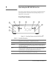
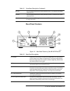
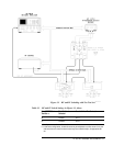
In the recommended configuration, the device is an HP 11713A attenuator/switch driver. The
switch/driver in turn controls one or more coaxial switches. These switches, (shown in a
Figure 3-3, and Figure 3-4) are used to choose which test set receives the RF output from the
network analyzer source.
The exact command issued depends upon the new value of the
{HP-IB ADDRESS}
{TEST SET}
value, also shown in shown in a Figure 3-3 and Figure 3-4.