


6-6
HP 8517B S-Parameter Test Set Manual
HP 8517B Test Set Replacement Procedures
Assembly Replacement Procedures
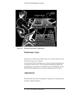
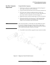
6. Unplug the four harnessed (multi-colored) wire and socket assemblies.
7. Lift the frequency converter out of the test set.
8. Remove the frequency converter bracket by removing the two Pozidriv
screws.
Regulator Board
Replacement
A15 Regulator Board Assembly
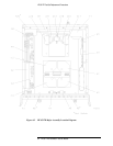
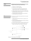
1. See Figure 6-2 for component locations.
2. Unplug the transformer socket from the regulator board.
3. Unplug the amplifier socket from the regulator board (only in Options
007, Option 002 “plus” 007, and Option 004 “plus” 007).
4. Remove the three mounting screws from the top edge of the regulator
board.
5. Remove the regulator board. (You may need to partially back out one of
the transformer mounting screws for clearance.)
Filter Capacitor
Replacement
C1 to C4 Filter Capacitors
1. With the test set in an upright position, pull the metal and plastic cover
off the 4 capacitors. See Figure 6-2 for the location of the filter
capacitors.
2. Turn the test set over and remove the bottom cover.
3. To discharge the capacitors, do the following:
a. Attach one end of an insulated clip lead to the chassis of the
instrument.
b. Attach the other end of the clip lead to a 100 Þ
Ω 20-watt resistor.
c. Use the resistor to discharge each capacitor terminal (the large
Pozidriv screw on the bottom side of the test set). Each capacitor has
two terminals.
d. Discharge all capacitor terminals. It takes approximately six seconds
per capacitor to discharge.
4. To remove a capacitor, remove the corresponding pair of screws and pull
the capacitor out of the test set.