


2-6
HP 8517B S-Parameter Test Set Manual
Installation
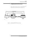
Configuring the Test Set in a System
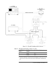
Connecting the System
Cables
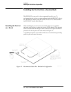
Replacing O-Rings in
Anti-Rotation Clamps
The anti-rotation clamp’s internal O-ring is a field-replaceable part. There is
no need to disassemble the anti-rotation clamp.
When the O-ring no longer holds the RF cable securely, replace it by
following the instructions in Chapter 6, “Replacement Procedures.”
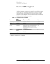
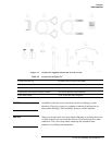
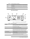
Table 2-2 Connection Instructions and Connector Descriptions
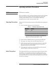
Connect System Power
and Control Cables
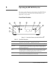
Check the test-set line module (see item (1) in Chapter 3, Figure 3-2 of this manual). It must be set for
the correct voltage in your region. Refer to Chapter 5, “Troubleshooting” of this manual for information
about changing the voltage selection or replacing the line fuse.
• After setting or confirming the line-voltage module, connect the test set power cord to an electrical
outlet.
• Attach the HP 8517B IF-interconnect cable from J11 TEST SET INTERCONNECT (on the test set’s
rear panel) to J1 TEST SET INTERCONNECT on the rear panel of the HP 85102 IF detector.
• Attach the system bus cable from HP 8517B J12 HP 8510 SYSTEM BUS connector to HP 8510C
INTERCONNECT on the HP 85101 display/processor.
The test set IF interconnect cable and the system bus cable transmit control signals between the test
set and the network analyzer.
Signal Path Connections The IF interconnect cable transmits IF signals from the test set to the HP 85102 IF detector.
• Attach one end of the 2.4 mm RF cable (item 9 or 10, Figure 2-1) to the RF output on the rear panel
of the HP 83651 Synthesized Sweeper.
• Attach the other end of the RF cable to the RF input on the HP 8517B Test Set.
Test Port Connectors Port 1 and Port 2 are male, NMD-2.4 mm connectors, and mate to female 2.4 mm connectors.
Anti-Rotation Clamps Use the anti-rotation clamps (item 5, Figure 2-1) to stabilize the test port or RF cable at the
connection, or to stabilize an adapter at the connection.
• Connect test port cables or adapters to the test ports.
• Torque the connections to 90 N-cm (8 in lb).
• Loosen the anti-rotation clamp thumb screw enough to slip the clamp over the cable and up to the
front panel. The clamp end with the flats should come to rest on the flats of the test port shoulder.
• Finger-tighten the thumb screws to prevent further loosening or tightening of the test port/RF cable
connection. Refer to Chapter 3, “Operation” of this manual for additional information.