


HP 8517B S-Parameter Test Set Manual
3-15
Using Anti-Rotation Clamps
During the performance verification procedure, use anti-rotation clamps to
secure RF connections at the test ports of each test set. While installed, each
clamp stabilizes the connector on RF cable to the large nut on the test set’s
RF test port. If an adapter is used, the clamp stabilizes the adapter to the
front panel RF port connector.
Without these clamps, the test port connections can loosen when a device
under test is moved. As a result, the loosening can invalidate calibrations and
measurements.
NOTE
These instructions refer to an installation using HP RF cables. However, the
anti-rotation clamps may also be used with front panel adapters. Adapter
installations are similar. There are two anti-rotation clamps included in the
test set accessories box.
Attach the first clamp
Remove one anti-rotation clamp from the accessories box. Loosen its
thumb-screw until it is nearly freed from the counter-sink socket in the
clamp body. The clamp is shown as item (5) in Figure 2-1, “Accessories
Supplied with the HP 8517B Test Set.”
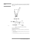
1. Gently push the clamp (round-hole end first) over and past the RF cable
connector to be used.
2. Fit the rubber O-ring in the round end of the clamp over the connector.
NOTE
If the O-ring is not snug or is damaged, refer to the Chapter 6, “Replacement
Procedures” for instructions about replacing the internal O-ring.
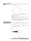
3. Wiggle the clamp to ease it over the connector.
4. Attach the cable to the test port and tighten it as specified in the cable
manual.
NOTE
Do not twist the cable as you attach it to the test port.
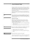
Use the torque wrench supplied with your calibration kit to tighten the cable
to 90 N-cm (8 in-lb). Do not over-torque the connection. See Figure 3-5.