


5-2
HP 8517B S-Parameter Test Set Manual
Troubleshooting the Test Set
Theory of Operation
Theory of Operation
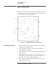
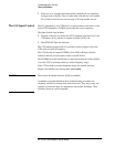
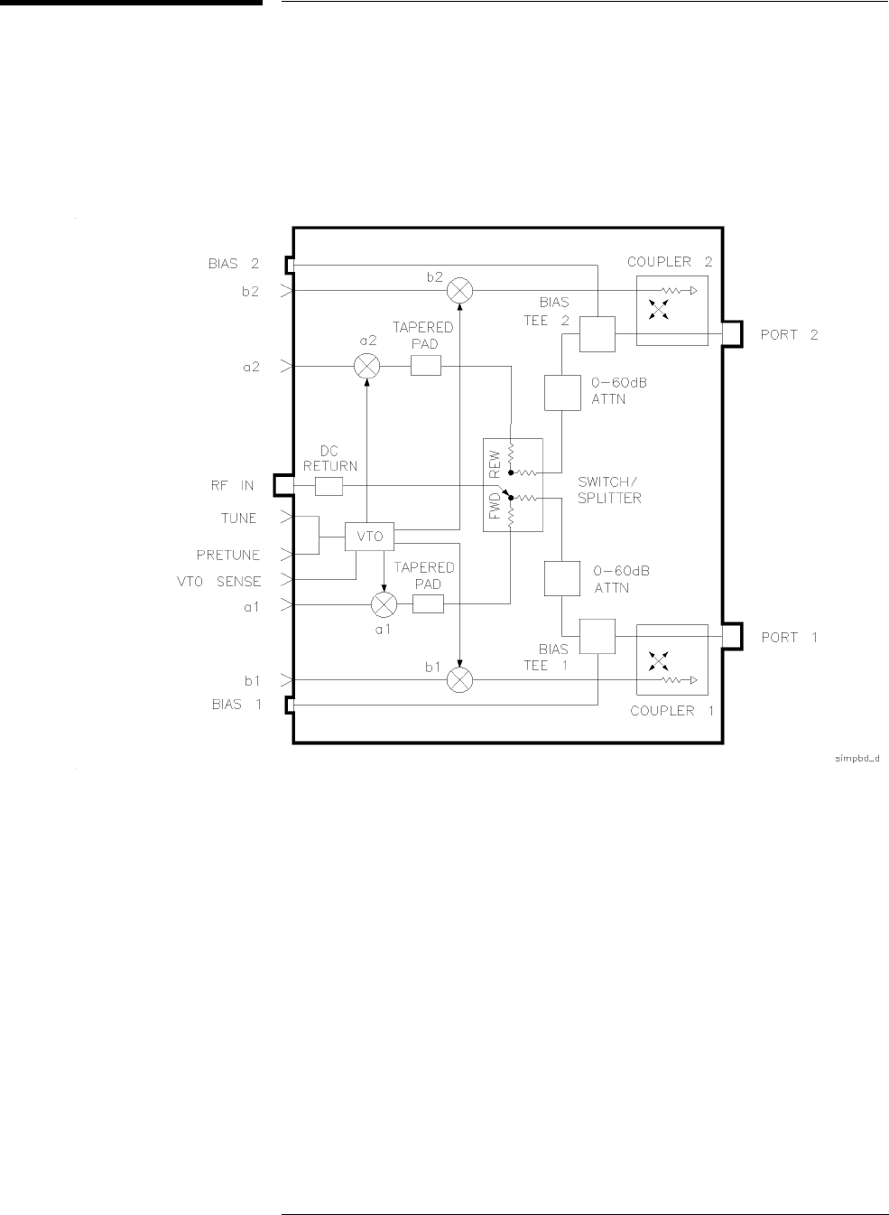
RF paths for Port 1 and Port 2 are similar. This section discusses in detail the
source power signal, as it is routed via the RF IN connector, through the test
set, and to Port 1 for S
11
and S
21
measurements.
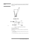
Figure 5-1 Standard HP 8517B RF Block Diagram
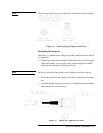
TheRFSourcePower • RF source power enters the test set through the rear panel. The RF power
is applied to the switch/splitter (A18).
• At the switch/splitter, the power is attenuated by approximately 7 to
14 dB, depending upon frequency.
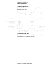
• The switch/splitter receives its control signals from the attenuator/switch
driver board (A5).
• The switch part of the switch/splitter, which is a combination of two
power splitters and a solid-state switch, selects the power splitter to use
and, therefore, the test port to receive the RF power.
• LEDs on the front panel and on the attenuator/switch driver board (A5)
indicate which test port is active.