


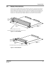
Component Details
GR2K-GA-1002 3-7
Rev. 6.03
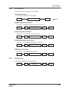
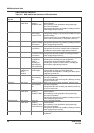
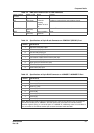
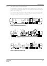
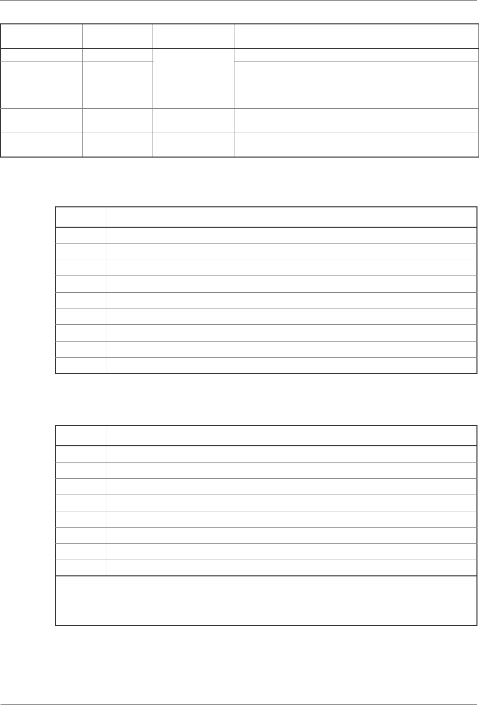
LINE ERR LED: Yellow Yellow: Line section II/W fault detection.
T/R LED: Green Shows the
operating
condition of each
line.
Conditions of transmission and reception signals.
LAMP TEST Switch
(Non-Lock)
Lamp test Press: LED’s on all the boards are lit.
REST Switch
(Non-Lock)
Manual resetting
the device
Reset.
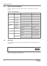
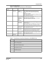
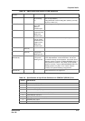
Table 3-4 Specifications of 9-pin D-sub Connector on CONSOLE (RS232C) Port
Pin No. Specifications
7 Request to send (RS) output
8 Clear to send (CS) input
6 Data set ready (DR) input
4 Data terminal ready (ER) output
1 Carrier detect of data channel receive (CD) input
9 Called indicator (CI) input
5 Signal ground or common line (SG)
3 Send data (SD) output
2 Receive data (RD) input
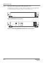
Table 3-5 Specifications of 8-pin RJ45 Connector on 10BASE-T/100BASE-TX Port
Pin No. Specifications
1 Transmit (+) (TA)
2 Transmit (-) (TB)
3Receive(+)(RA)
4Unused(UA)
5Unused(UB)
6Receive(-)(RB)
7Unused(UC)
8Unused(UD)
Note: Because the interface cable is of twisted-pair type, make TA and TB into a pair, and make RA
and RB into another pair on 10BASE-T; the other pins can be connected to one another without
particular regard to pairing, or can be left open. On 100BASE-TX, additionally make UA and UB into a
pair, and make UC and UD into another pair to cause termination within the RMP.
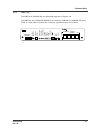
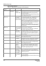
Table 3-3 RMP switch and function of LED indications
Name of switch
and LED
Switch or LED Status Content