


Product Overview
GR2K-GA-1002 2-23
Rev 6.03
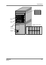
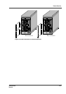
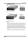
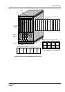
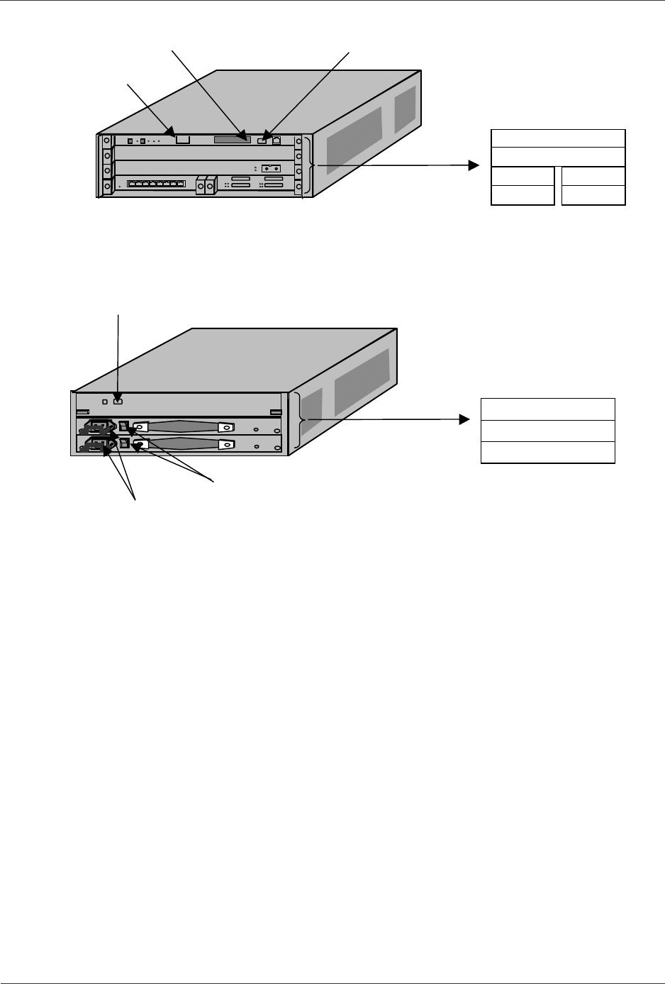
Figure 2-31 Front View of GR2000-4S
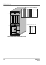
Figure 2-32 Rear View of GR2000-4S
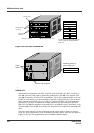
GR2000-6H
This model incorporates one BCU, one RP, and one POW; the BCU consists of one
RM and one CSW, and is physically packaged in one RM-CPU module and one
RM-IO module. One BCU for redundancy, up to two additional RPs, and one POW
for redundancy can be installed as options, independently of one another. Since
one RP can handle up to two NIFs, a total of six NIFs can be installed on this
model. The BCU redundancy is made available by mounting the optional
RM-CPU and RM-IO modules in the RM-CPU1 and RM-IO1 slots; otherwise, only
thebaseRM-CPUandRM-IOmodulesaremountedintheRM-CPU0andRM-IO0
slots. Similarly, the power supply redundancy is made available by mounting the
optional POW in the POW1 slot; otherwise, only the base POW is mounted in the
POW0 slot.
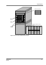
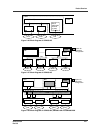
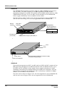
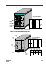
The front view is shown in Figure 2-33, the front appearance view of GR2000-6H,
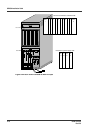
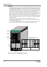
and the rear view in Figure 2-34, the rear appearance view of GR2000-6H.
Memory card slot
LED (status
indicator)
3
88
NIF3
NIF0
NIF2
NIF1
R
M-IO
RP
RS-232C port (for console)
Mounting position of
RMP-IO, RP and NIF
board.
POW1
POW0
RM-CPU
Power switch
Power cord receptacle
RS-232C port (for AUX)
Mounting position of
RM-CPU board and
power supply unit
(device integrated type)