


GR2000 Installation Guide
2-6 GR2K-GA-1002
Rev 6.03
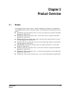
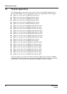
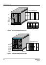
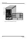
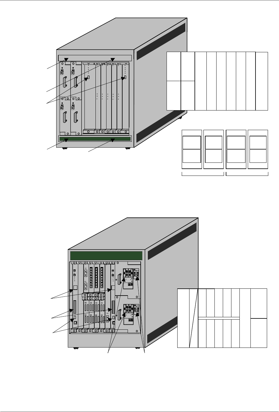
Figure 2-8 Rear View of GR2000-10H with AC Input
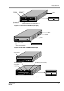
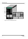
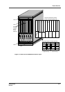
Figure 2-9 Front View of GR2000-10H with DC Input
Placement of RM-CPU and RP
boards, and power supply units:
RP
4
RP
3
RP
2
RP
0
RP
1
RM-
CPU
0
RM-
CPU
1
DC-DC
1
DC-DC
0
DC-DC
3
DC-DC
2
RS-232C
connector
(for AUX)
None in
case of
RMB-CPU
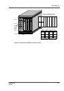
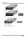
FAN3
FAN1
FAN2
FAN0
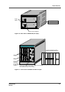
Placement of fans in fan tray (top view):
Fan 4
(main)
Fan 2
(power)
Fan 3
(main)
Fan 1
(power)
(front)
(rear)
Upper fan tray
(front)
(rear)
FAN1
FAN3
Fan 4
(main)
Fan 2
(power)
Fan 3
(main)
Fan 1
(power)
(front)
(rear)
Lower fan tray
(front)
(rear)
FAN0
FAN2
3
0
88 88
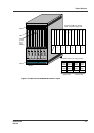
NIF
5
NIF
4
NIF
6
NIF
7
NIF
8
NIF
9
RM-
IO1
NIF
0
NIF
1
NIF
2
NIF
3
LED (status
indicator)
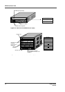
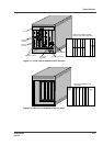
Placement of RM-IO and NIF
boards, and power supply units:
RS-232C
connector
(for console)
Two (CONSOLE
&AUX)incase
of RMB-10
Memory
card slot
Terminal block
Power breaker
RM-
IO0
PS
INPUT1
(DC)
PS
INPUT0
(DC)