


GR2000 Installation Guide
3-12 GR2K-GA-1002
Rev. 6.03
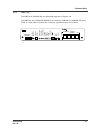
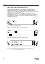
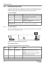
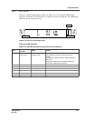
Switch and LED indication
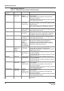
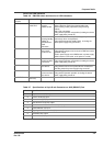
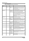
Table 3-8 RM-IO switch and function of LED indications
Name of switch
and LED
Switch or LED Status Content
STATUS LED: Green/
Yellow/ Red
Shows the
operating
condition of RM.
Green: Operable operation
Yellow: Blocking and cock insertion and removal possible.
Green blinking: Under preparation (being started up.)
Red: Fault or shutdown
Extinguished: Operation not possible (Including the device
power supply being turned off)
EMA SUPPRESS
(GR2000-4S)
LED: Yellow Shows the state of
EMA SUPPRESS
key, and the
system switching
suppressionstate.
Yellow: If both of the operation and standby systems or
only the operation system are lit, it shows that the system
is in switching suppression state according to the
instructions of turning the operation system EMA
SUPPRESS switch on or EMA SUPPRESS by means of
software. If only the standby system is lit, since it shows
that the EMA SUPPRESS switch of the standby system is
turned on, keep the switch turned off. In this case, the
system switching is not suppressed.
Extinguished: Shows that it is not in the system switching
suppression state. (Including the device power supply
being turned off.)
ACTIVE
(GR2000-4S)
LED: Green Shows the state of
operation/standby
of the duplicated
section.
Green: Shows the state of operation. (Lights up
continuously when not duplicated.)
Extinguished: Shows the standby state. (Including the
device power supply being turned off.)
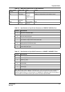
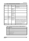
POWER LED: Green Shows the state of
power supply
turned on or off.
Green: Voltages of 5V and 3.3V of RMP are normal.
Extinguished: Voltages of 5V and 3.3V of RMP are not the
specified voltage. (Fault in power supply unit or RMP
board, or power supply switch in device is turned off, or AC
power is not fed.)
READY LED: Green Shows the
operablecondition
of the device.
Green blinking: Operable operation
Extinguished: Operation not possible (Including the device
power supply being turned off)
ERROR LED: Yellow Shows partial fault
in the device.
Yellow: Partial fault has been developed in the device.
Extinguished: Occurrence of partial fault is not detected.
(Including the device power supply being turned off.)
ALARM LED: Red Shows
occurrenceof fault
in the device.
Red: Partial fault has occurred in the device.
Extinguished: Operation possible. (Including the device
power supply being turned off.)
POST DISP LED: Green Shows the state
that STATUS
CODE is
indicating the
initial diagnosis
code of RM-CPU.
Green blinking: Shows the state that STATUS CODE (7
seg) is indicating the initial diagnosis code of RM-CPU.
Extinguished: Shows that STATUS CODE (7 seg) is
indicating the contents of FAULT CODE. (Including the
device power supply being turned off.)
STATUS CODE 7seg: Green 7 seg for
indicating the
device condition.
7 seg. Decimal
and two digits.
Green blinking: Indicates the device state code for 00~99.
(Code contents differ by lighting of POST DISP LED.)
Extinguished: Non-indication. (Including the device power
supply being turned off.)
ACCESS 0 LED: Green Shows the state of
MC card being
zero.
Blinking: MC card zero being accessed. (Memory card
take-out is prohibited.)
Extinguished: MC card zero being idle. (Memory card may
be put in or taken out.)