


GR2000 Installation Guide
3-22 GR2K-GA-1002
Rev. 6.03
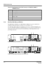
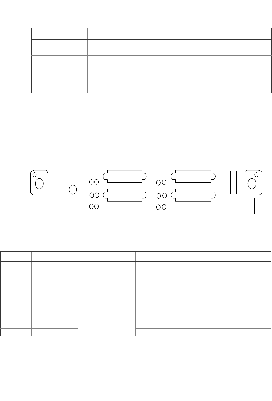
3.5.4 NWVX-4
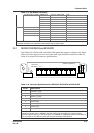
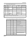
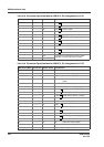
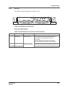
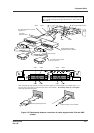
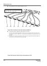
The NWVX-4 physically appears as Figure 3-25. This NIF has four ports for V.24/
X.21/V.35 connections via half-pitched 50-pin connectors on the router side, which
require specific connector pin assignments for respective interfaces. See Table 3-23,
Table 3-24, and Table 3-25 for the connector specifications.
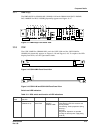
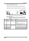
Figure 3-25 NWVX-4 Front Panel View
Switch and LED indication
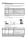
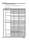
Table 3-20 Connector Specifications for NE1G-1S, NE1G-1SA, NE1G-1L, NE1G-1LA,
NE1G-1LHA, NE1G-1LHA8, NE1G-1SB, NE1G-1LB and NE1G-1LHBA
NIF Connector Specifications
NE1G-1S, NE1G-1SA,
NE1G-1SB
SC 2-core (flat) connector (multimode fiber, 850 nm wavelength)
NE1G-1L, NE1G-1LA,
NE1G-1LB
SC 2-core (flat) connector (multimode/single-mode fiber, 1300 nm wavelength)
NE1G-1LHA,
NE1G-1LHA8,
NE1G-1LHBA
SC 2-core (flat) connector (multimode/single-mode fiber, 1500 nm wavelength)
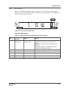
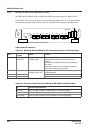
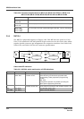
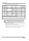
Table 3-21 NWVX-4 switch and function of LED indications
Name LED: Color Status Content
STATUS LED: Green/
Yellow/ Red
Shows the operating
condition of NIF
Green: Operable operation
Yellow: Blocking and the board replaceable state.
Green blinking: Under preparation (Program being
loaded.)
Red: Fault
Extinguished: Operation not possible (Including the
device power supply being turned off)
T/R LED: Green Shows the operating
condition of each line.
LED: Green
Green: State of transmission and reception signals in line.
ACT LED: Green Line operation (open) state.
LINE ERR LED: Yellow Yellow: Line fault detection.
NWVX-4
LINE0
LINE1
L
INE3
LINE ERR
A
CT
T/R
STATUS
LINE3
L
INE2
LINE1
LINE0
V.24
V.35
X.21
LINE2