GR2000 Installation Guide
2-18 GR2K-GA-1002
Rev 6.03
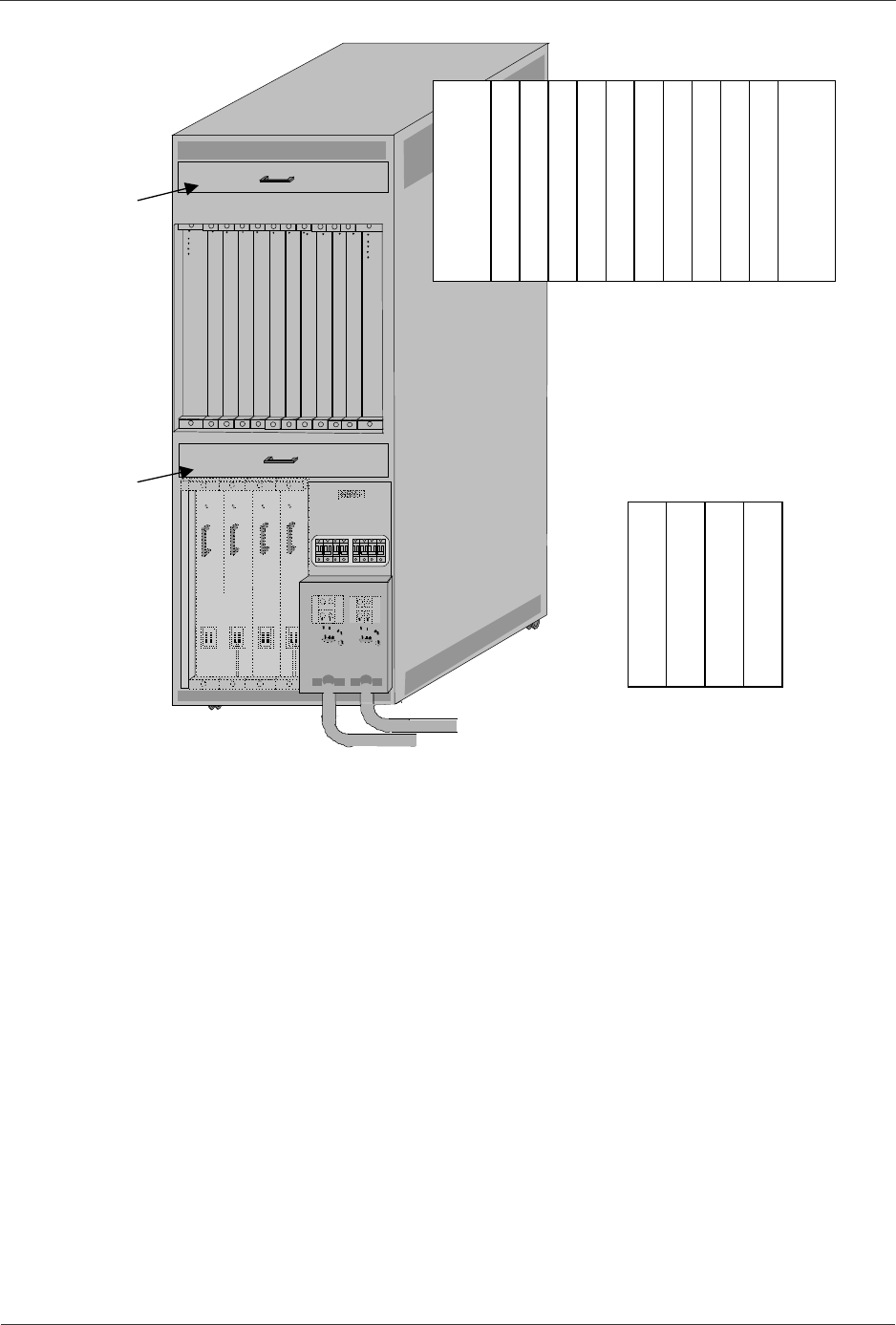
Figure 2-24 Rear View of GR2000-20 with DC Input
Placement of RM-CPU and RP boards:
RM-
CPU
0
RP
4
RP
3
RP
2
RP
0
RP
1
RM-
CPU
1
RP
9
RP
8
RP
7
RP
5
RP
6
Power
Unit
1-1
Power
Unit
1-0
Power
Unit
0-1
Power
Unit
0-0
Placement of power supply units:
Fan
F
an


