GR2000 Installation Guide
3-8 GR2K-GA-1002
Rev. 6.03
3.3.3 RM-CPU(4S), RMB-CPU (4S), RM-CPU(HH), RMB-CPU (HH), RM-CPU(MH),
RMB-CPU (MH), RM-CPU(LH) and RMB-CPU (LH)
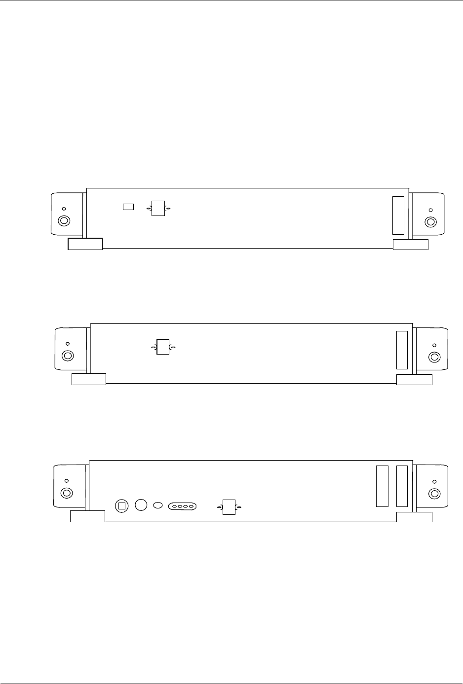
The RM-CPU(4S) and RMB-CPU (4S) for GR2000-4S, the RM-CPU(HH) and
RMB-CPU (HH) for GR2000-6H, the RM-CPU(MH) and RMB-CPU (MH) for
GR2000-10H, and the RM-CPU(LH) and RMB-CPU (LH) for GR2000-20H physically
appear as Figure 3-7 through Figure 3-9.
The RM-CPU(4S), the RMB-CPU (4S), the RM-CPU(HH) RMB-CPU (HH), the
RM-CPU(MH) RMB-CPU (MH), and the RM-CPU(LH) RMB-CPU (LH) each have one
AUX (RS232C) port for the console connection. Table 3-5 shows the connector
specifications on this port.
Figure 3-7 RM-CPU(4S), RMB-CPU (4S) Front Panel View
Figure 3-8 RM-CPU(HH) RMB-CPU (HH) Front Panel View
Figure 3-9 RM-CPU(MH) RMB-CPU (MH) or RM-CPU(LH) RMB-CPU (LH)
Front Panel View (GR2000-10H/20H)
R
M-CPU(4S)
V
-CHK
AUX(RS232C)
Note: AUX not used in case of RMB-CPU (4S).
R
M-CPU(HH)
AUX(RS232C)
Note: AUX not used in case of RMB-CPU (HH).
LAMPTEST
STATUS
POWER
READY
ERROR
A
LARM
ACTIVE
M-CPU (MH)
A
UX
(
RS232C)
or
M-CPU (LH)
Note: AUX not used in case of RMB-CPU (MH) and RBM-CPU(LH).


