


this connection work requires expertise, the work must be conducted by qualified
personnel. The steps are as follows:
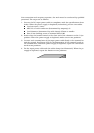
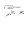
1. Procure the DC input power cable in compliance with the specifications show
below. When the power supply is duplexed (redundant), procure two cables.
Cord structure: 3-wire
AWG No. of each conductor (determined by ampacity): 6
Cord diameter (determined by cable clamp): 27mm or smaller
Size of wire-binding screw on terminal board: M5
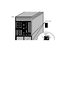
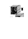
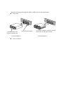
2. Ensure that the breaker switch in the rear end of the chassis is in the O (out
position. When the power supply is duplexed, make sure in two positions.
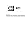
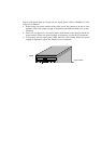
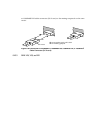
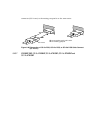
3. Detach the cover from the input unit and connect each terminal wire of the in
power cable firmly to the terminal board and the ground. See Figure 6-60 for
dimensions of the terminal board and the terminal wire. When the power sup
is duplexed, repeat the connection work in two positions.
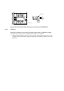
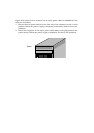
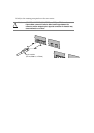
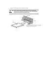
4. Fix the input power cable with the cable clamp. When the power supply is
duplexed, repeat the fixation in two positions. Then, attach the cover back to
input unit.