


Component Details
GR2K-GA-1002 3-15
Rev. 6.03
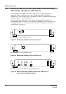
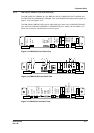
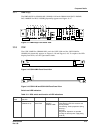
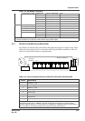
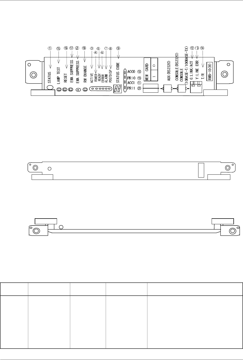
3.3.7 RMB-IO(H)
The RMB-IO(H) for GR2000-6H, GR2000-10H and GR2000-20H (BCU-H850H,
BCU-M850H and BCU-L850H) physically appears as Figure 3-17
Figure 3-17 RMB-IO(H) Front Panel View
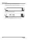
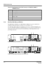
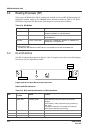
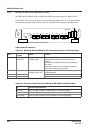
3.3.8 CSW
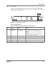
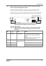
The CSW-L3MH for GR2000-20H, and the CSW-L1M and the CSW-L3M for
GR2000-20 physically appear as Figure 3-18 and Figure 3-19. To explore the LED
display functions, see the Operations Guide.
Figure 3-18 CSW-L3MH Front Panel View
Figure 3-19 CSW-L1M and CSW-L3M Front Panel View
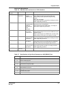
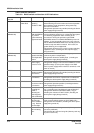
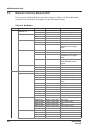
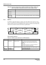
Switch and LED indication
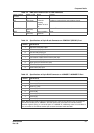
Table 3-11 BCU switch and function of LED indications
Nam of
Board
Name of switch
and LED
Switch or LED Status Content
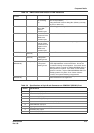
CSW STATUS
(GR2000-4/10)
LED: Green/
Yellow/ Red
Shows the
operating
condition of RM.
Green: Operable operation
Yellow: Blocking and cock insertion and
removal possible.
Green blinking: Under preparation (being
started up.)
Red: Fault
Extinguished: Operation not possible
(Including the device power supply being
turned off)
S
TATUS
CSW(LH)
STATUS