Component Details
GR2K-GA-1002 3-21
Rev. 6.03
3.5.3 NE1G-1S, NE1G-1SA, NE1G-1L, NE1G-1LA, NE1G-1LHA, NE1G-1LHA8,
NE1G-1LB, NE1G-1SB and NE1G-1LHBA
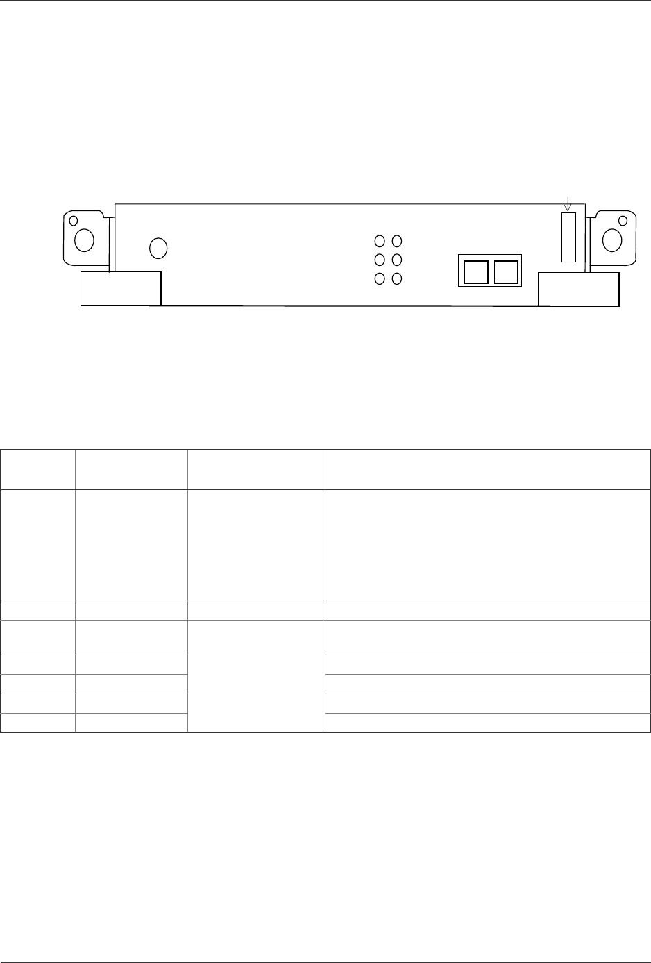
The NE1G-1S, NE1G-1SA, NE1G-1L, NE1G-1LA, NE1G-1LHA, NE1G-1LHA8,
NE1G-1LB, NE1G-1SB and NE1G-1LHBA physically appear as Figure 3-24.
These NIFs each have one port for connection with a pair of SC 2-core optical fiber
connectors (transmit and receive). Table 3-20 shows the connector specifications.
Figure 3-24 NE1G-1S, NE1G-1SA, NE1G-1L, NE1G-1LA, NE1G-1LHA, NE1G-1LHA8,
NE1G-1SB, NE1G-1LB and NE1G-1LHBA Front Panel View
Switch and LED indication
Table 3-19 NE1G-1S, NE1G-1SA, NE1G-1L, NE1G-1LA, NE1G-1LHA, NE1G-1LHA8,
NE1G-1LB, NE1G-1SB and NE1G-1LHBA switch and function of LED
indications
Name
Name of switch
and LED
Status Content
STATUS LED: Green/
Yellow/ Red
Shows the operating
condition of RM.
Green: Operable operation
Yellow: Blocking and the board replaceable state.
Green blinking: Under preparation (Program being
loaded.)
Red: Fault
Extinguished: Operation not possible (Including the
device power supply being turned off)
LINE LED: Green Green: Ring pulse being established
ACT LED: Green Shows the operating
condition of each line.
Green: Line operation possible state (line open state)
LINE ERR LED: Yellow Yellow: Line section II/W fault detection.
R LED: Green Frame signal being received.
T LED: Green Frame signal being transmitted.
SIG-DT LED: Green Signal detect operation detected.
R
T
SIG-DT
LINK
ACT
LINE ERR
ST
AT
U
S
NE1G-1**
LINE 0
T
R
1000BASE-SX or
1000BASE-LX or
1000BASE-LH
Mark ** indicates 1S, 1SA, 1SB, 1L,
1LA, 1LB, 1LHA, 1LHAB, and 1LHBA.


