GR2000 Installation Guide
3-20 GR2K-GA-1002
Rev. 6.03
3.5.2 NE100-4F, NE100-4FS, and NE100-4FS4
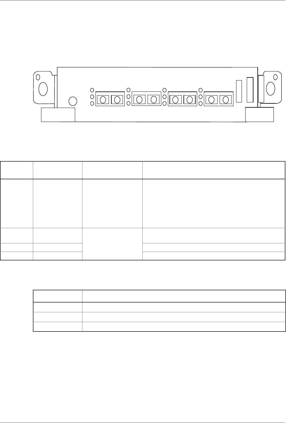
The NE100-4F, NE100-4FS, and NE100-4FS4 physically appear as Figure 3-23.
These NIFs each have four ports for connection with pairs of SC 2-core optical fiber
connectors (transmit and receive). Table 3-18 shows the connector specifications.
Figure 3-23 NE100-4F, NE100-4FS, and NE100-4FS4 Front Panel View
Switch and LED indication
Table 3-17 NE100-4F/NE100-4FS/NE100-4FS4 switch and function of LED indications
Nam
Name of switch
and LED
Status Content
STATUS LED: Green/
Yellow/ Red
Shows the operating
condition of RP.
Green: Operable operation
Yellow: Blocking and cock insertion and removal
possible.
Green blinking: Under preparation (being started up.)
Red: Fault
Extinguished: Operation not possible (Including the
device power supply being turned off)
LINK LED: Green Shows the operating
condition of each line.
Ring pulse of 100BASE-FX/FX (middle)/FX (long) is
being established.
LINE ERR LED: Red
T/R LED: Green
Table 3-18 Connector Specifications for NE100-4F, NE100-4FS, and NE100-4FS4
NIF Connector Specifications
NE100-4F SC 2-core (flat) connector (multimode fiber, 1300 nm wavelength)
NE100-4FS SC 2-core (flat) connector (single-mode fiber, 1300 nm wavelength)
NE100-4FS4 SC 2-core (flat) connector (single-mode fiber, 1300 nm wavelength)
STATUS
NE100-4FS
100BASE-FX
RXTX
LINE 0
NE100-4FS4
NE100-4F
LINE ERR
LINK
T/R
RXTX
LINE 1
RXTX
LINE 2
RXTX
LINE 3
or
or


