3 - 5
Scanner LED Sequences and Meaning
Note: Pressing the button on the scanner causes the LED to glow red until it communicates successfully with the base.
Base LED Sequences and Meaning
The base contains a red LED that indicate the status of the unit and verifies its communication with the host system. The
base also has a green LED that indicates the scanner battery charge condition.
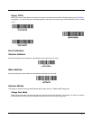
Base Power Communication Indicator
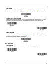
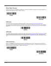
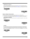
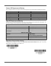
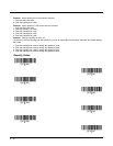
To display the power indicator on the base, scan the Base Power Communication Indicator On bar code. To turn off the
power indicator, scan the Off bar code. Default = On.
LED Indication Beeper Indication Cause
Normal Operation
Red Flash None Battery low
Green Flash 1 beep Successful communication or linking
Red, blinking Razz or error tone Failed communication
Menu Operation
Green Flash 2 beeps Successful menu change
Red, blinking Razz or error tone Unsuccessful menu change
Red LED - Host Communication
Red LED Communication Condition
Off Power off, USB suspend
On continuously Power on, system idle
Short blinks. Occurs while transferring data to/from the RF module
or the host port.
Receiving data
Green LED - Scanner Battery
Green LED Charge Condition
Off Battery not detected or charge suspended
Slow flash, 1 second on, 1 second off Pre-charge and charging
On continuously Charge complete
Fast flash, 300 mSec on, 300 mSec off Charge Error
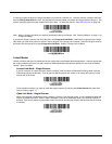
* Base Power Communication
Indicator On
Base Power Communication
Indicator Off


