


EM78P312N
8-Bit Microcontroller
Product Specification (V1.0) 10.03.2006
• 9
(This specification is subject to change without further notice)
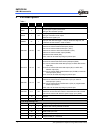
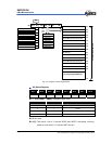
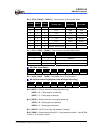
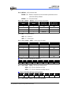
Bit 4 ~ Bit 2 ( TC4CK2 ~ TC4CK 0 ) : Timer/Counter 4 Clock Source Select
TC4CK2 TC4CK1 TC4CK0
Clock Source
( Normal, Idle )
Resolution
( Fosc=8M )
Max. Time
( Fosc=8M )
0 0 0 Fc/2
11
256μS 65mS
0 0 1 Fc/2
7
16μS 4mS
0 1 0 Fc/2
5
4μS 1mS
0 1 1 Fc/2
3
1μS 255μS
1 0 0 Fc/2
2
500nS 127.5μS
1 0 1 Fc/2
1
250nS 63.8μS
1 1 0 Fc 125nS 31.9μS
1 1 1 External clock (TC4 pin) − −
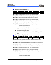
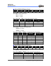
Bit 1 ~ Bit 0 ( TC4M1 ~ TC4M0 ) : Timer/Counter 4 Operating Mode Select
TC4M1 TC4M0 Operating Mode
0 0 Timer/Counter
0 1 Reserved
1 0 Programmable Divider output
1 1 Pulse Width Modulation output
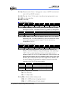
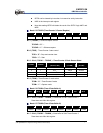
RC (Timer 4 Data Buffer)
Bit 7 Bit 6 Bit 5 Bit 4 Bit 3 Bit 2 Bit 1 Bit 0
TC4D7 TC4D6 TC4D5 TC4D4 TC4D3 TC4D2 TC4D1 TC4D0
Bit 7 ~ Bit 0 ( TC4D7 ~ TC4D0 ) : Data buffer of 8-bit Timer/Counter 4.
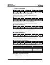
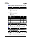
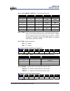
RD (Interrupt Status Flag Register 0 and INT3 Edge Detect Flag)
Bit 7 Bit 6 Bit 5 Bit 4 Bit 3 Bit 2 Bit 1 Bit 0
0 0 INT3F INT3R 0 0 WDTIF EXIF0
Bit 5 ( INT3F ) : External Interrupt 3 falling edge detect flag.
INT3F = “0” : Falling edge is not detected
INT3F = “1” : Falling edge is detected
Bit 4 ( INT3R ) : External Interrupt 3 rising edge detect flag.
INT3R = “0” : Rising edge is not detected
INT3R = “1” : Rising edge is detected
Bit 1 ( WDTIF ) : WDT time-out flag, flag cleared by software.
Bit 0 ( EXIF0 ) : External interrupt flag (INT0). Flag cleared by software. If the INT0EN
is reset to “0”, the flag is cleared.