


EM78P312N
8-Bit Microcontroller
40 •
Product Specification (V1.0) 10.03.2006
(This specification is subject to change without further notice)
8-bit Up-counter
Comparator
TCR4
TC4CR
MUX
TC4 pin
TC4CK
TC4S
3
TC4 Interrupt
fc/2
11
fc/2
7
fc/2
3
Clear
TC4M (1,1)
TC4M(1,*)
TC4FF
Toggle
Set
Clear
/PWM, /PDO Pin
Overflow
Match
F/F
Q
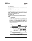
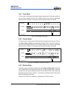
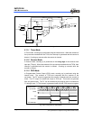
Fig. 5-24 Timer/Counter 4 Configuration
5.11.1 Timer Mode
In Timer mode, counting up is performed using the internal clock. When the contents of
the up-counter matched with the TCR4, then interrupt is generated and the counter is
cleared. Counting up resumes after the counter is cleared.
5.11.2 Counter Mode
In Counter mode, counting up is performed on the rising edge of the external clock
input pin (TC4 pin). When the contents of the up-counter matched with the TCR4, then
interrupt is generated and the counter is cleared. Counting up resumes after the
counter is cleared.
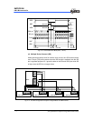
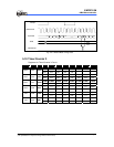
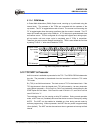
5.11.3 PDO Mode
In Programmable Divider Output (PDO) mode, counting up is performed using the
internal clock. The contents of TCR4 are compared with the contents of the
up-counter. The F/F output is toggled and the counter is cleared each time a match is
found. The F/F output is inverted and output to /PDO pin. This mode can generate
50% duty pulse output. The F/F can be initialized by the program and it is initialized to
“0” during a reset. A TC4 interrupt is generated each time the /PDO output is toggled.
01 3
n-1
n
0
n-1
n
01 n-1
012
Source Clock
Up-counter
TCR4
TC4 Interrupt
n
21
n
F/F
/PDO Pin
Fig. 5-25 Timing Chart for PDO Mode