


EM78P312N
8-Bit Microcontroller
30 •
Product Specification (V1.0) 10.03.2006
(This specification is subject to change without further notice)
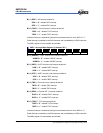
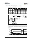
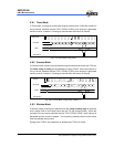
3. Start transmitting.
4. Serially transmitted data are transmitted in the following order from the TX pin.
5. Start bit: one “0” bit is output.
6. Transmit data: 7, 8 or 9 bits data are output from the LSB to the MSB.
7. Parity bit: one parity bit (odd or even selectable) is output.
8. Stop bit: one “1” bit (stop bit) is output.
Mark state: output “1” continues until the start bit of the next transmitted data.
After transmitting the stop bit, the UART generates a TBEF interrupt (if enabled).
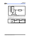
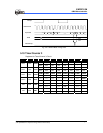
5.7.3 Receiving
In receiving, the UART operates as follows:
1. Set RXE bit of the URS register to enable the UART receiving function.
The UART monitors the RX pin and synchronizes internally when it detects a start
bit.
2. Receive data is shifted into the URRD register in the order from LSB to MSB.
3. The parity bit and the stop bit are received.
After one character received, the UART generates a RBFF interrupt (if enable).
And URBF bit of URS register will be set to 1.
4. The UART makes the following checks:
(a) Parity check: The number of 1 of the received data must match the even or
odd parity setting of the EVEN bit in the URS register.
(b) Frame check: The start bit must be 0 and the stop bit must be 1.
(c) Overrun check: The URBF bit of the URS register must be cleared (that
means the URRD register should be read out) before next received data is
loaded into the URRD register.
If any checks failed, the UERRIF interrupt will be generated (if enabled), and an
error flag is indicated in PRERR, OVERR or FMERR bit. The error flag should be
cleared by software else the UERRIF interrupt will occur when the next byte is
received.
5. Read received data from URRD register. And URBF bit will be clear by hardware.
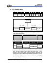
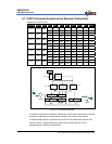
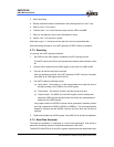
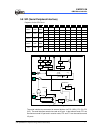
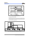
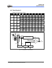
5.7.4 Baud Rate Generator
The baud rate generator is comprised of a circuit that generates a clock pulse to
determine the transfer speed for transmission/reception in the UART.
The BRATE2~BRATE0 bits of the URC1 register can determine the desired baud rate.