


EM78P312N
8-Bit Microcontroller
Product Specification (V1.0) 10.03.2006
• 43
(This specification is subject to change without further notice)
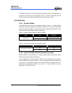
The Watchdog timer and prescaler are cleared.
Upon power on, the upper two bits of R3 are cleared.
Upon power on, the upper two bits of R4 are cleared.
Upon power on, the upper three bits of R5 are cleared.
The bits of CONT register are set to all “1” except Bit 6 (INT flag).
ISFR0, ISFR1, ISFR2 register and IMR1, IMR2 registers are cleared.
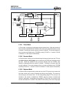
The controller has two modes for power saving.
(1) SLEEP mode: R5 (SIS) = 1, SLEP instruction.
The internal oscillator is turned off and all system operation is halted.
(2) Idle mode: R5 (SIS) = 0, SLEP instruction
The CPU core halts but the on-chip peripheral and oscillator circuit remain active.
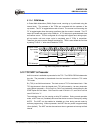
5.14.2 Wake-up from Sleep Mode
(1) External /SLEEP pin
The controller will be waken up and execute the next instruction after entering Sleep
mode. All the registers will maintain their original values before “SLEP” instruction was
executed.
(2) /RESET pin pull low
This will reset the controller and starts the program at address zero.
(3) WDT time out
This will reset the controller and run the program at address zero.
5.14.3 Wake-up from Idle Mode
(1) All interrupt
In all these cases, user should always enable the circuit before entering Idle mode.
After wake-up, all registers will maintain their original values before entering “SLEP”
instruction, then service an interrupt subroutine or proceed with next instruction by
setting individual interrupt enable bit. After servicing an interrupt sub-routine (“RETI”
instruction), the program will jump from “SLEP” instruction to the next instruction.
(2) /RESET pin pull low
This will reset the controller and run the program at address zero.
(3) WDT time out
This will reset the controller and run the program at address zero.