


EM78P312N
8-Bit Microcontroller
Product Specification (V1.0) 10.03.2006
• 1
(This specification is subject to change without further notice)
1 General Description
The EM78P312N is an 8-bit microprocessor with low-power, high-speed CMOS technology and high noise immunity. It
has an on-chip 4K×13-bits Electrical One Time Programmable Read Only Memory (OTP-ROM). It provides
multi-protection bits to prevent intrusion of user’s OTP memory codes. Seven Option bits are also available to meet
user’s requirements. With its OTP-ROM feature, the EM78P312N provides a convenient way of developing and verifying
user’s programs. Moreover, this OTP device offers the advantages of easy and effective program updates, using
development and programming tools. User can avail of the ELAN Writer to easily program his development code.
2 Features
CPU configuration
z 4K×13 bits on-chip ROM
z 144×8 bits on-chip registers (SRAM)
z 8-level stacks for subroutine nesting
z Less than 3.5mA at 5V/8MHz
z Typically 0.8 μA, during sleep mode
z Typically 1.1 μA, during idle mode
I/O port configuration
z 4 bidirectional I/O ports : P6, P7, P8, P9
z 22 I/O pins
z 10 Programmable pull-down I/O pins
z 10 programmable pull-high I/O pins
z External interrupt : P60, P61, P73, P80
Operating voltage range:
z OTP version
Operating voltage range:2.5v~5.5v
Operating temperature range:
z -40~85°C
Operating frequency range:
Main clock
• Crystal mode:
DC ~ 20MHz/2clks @ 5V; DC ~100ns inst. cycle @ 5V
DC ~ 8MHz/2clks @ 3V;DC ~ 250ns inst. cycle @ 3V
• ERC mode:
DC ~ 16MHz/2clks @ 5V;DC ~ 125ns inst. cycle @ 5V
DC ~ 8MHz/2clks @ 3V;DC ~ 250ns inst. cycle @ 3V
Peripheral configuration
z Serial peripheral interface (SPI) available
z Universal asynchronous receiver transmitter interface
(UART)available
z 16 bits Counter/Timer
TC2: Timer/Counter/Window
z 8 bits Timer/Counter
TCC: 8-bit real time clock/counter with overflow
interrupt
TC3: Timer/Counter/Capture
TC4: Timer/Counter/ PWM (pulse width modulation) /
PDO (Programmable divider output)
z 8-bit channels Analog-to-Digital Converter with 10-bit
resolution
z Time Base Timer:(1Hz~16kHz at 8MHz)
z Key tone output:(1kHz~8kHz at 8MHz)
z 8-bit channels Analog-to-Digital Converter with 10-bit
resolution
Fifteen available interrupts:
z WDT time-out interrupt
z TCC overflow interrupt
z Time base timer interrupt (the first falling edge of the
source clock)
z Serial UART transmit interrupt
z Serial UART receive interrupt
z Serial UART receive error interrupt
z Four External interrupt
z ADC completion interrupt
z TC2 overflow interrupt
z TC3 overflow interrupt
z TC4 overflow interrupt
z Serial SPI interrupt
Special features
z Programmable free running watchdog timer
z Two clocks per instruction cycle
z Power-on Reset
z High noise immunity
z Power saving Sleep mode
z Selectable Oscillation mode
Package type:
z 28-pin DIP 600 mil: EM78P312NP
z 28-pin Skinny DIP 300 mil: EM78P312NAK
z 28-pin Skinny DIP 400 mil: EM78P312N
z 28-pin SOP 300 mil: EM78P312NM
z 28-pin SSOP 209 mil: EM78P312NS
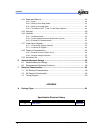
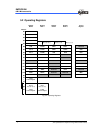
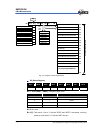
3 Pin Assignment
1
2
3
4
5
6
7
8
9
10
11
12
13
14 15
16
17
18
19
20
21
22
23
24
25
26
27
28
(ACLK) OSCO
OSCI
TEST
(AD0) P90
(AD1) P91
(AD2) P92
(AD3) P93
(AD4) P94
(AD5) P95
(AD6) P96
(AD7/VREF) P97
(TC3, INT3) P80
(TC4, /PWM, /PDO) P81
VSS
P70 (/SCK)
P71(RX,SI)
P72 (TX,SO)
P73 (/SLEEP, /INT5)
P60 (/INT0)
P61 (INT1)
P62 (TC2)
P63 (/TONE)
P64 (/SS)(OEB)
P65 (PGMB)
P66 (DATAIN)
P67 (DINCK)
/RESET (VPP)
VDD
EM78P312N
Fig. 3- Pin Assignment