


EM78P312N
8-Bit Microcontroller
20 •
Product Specification (V1.0) 10.03.2006
(This specification is subject to change without further notice)
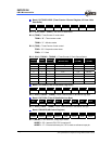
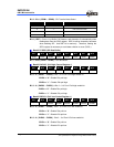
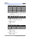
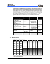
Bit 2 ( PSR2 ) ~ Bit 0 ( PSR0 ) : TCC prescaler bits
PSR2 PSR1 PSR0 Operating Mode
0 0 0 1:2
0 0 1 1:4
0 1 0 1:8
0 1 1 1:16
1 0 0 1:32
1 0 1 1:64
1 1 0 1:128
1 1 1 1:256
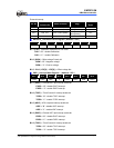
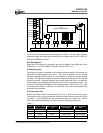
IOC6 ~ IOC9 − I/O Port Control Register
z "1" puts the relative I/O pin into high impedance, while "0" defines the relative
I/O pin as output.
z IOC6 and IOC9 registers are both readable and writable.
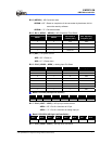
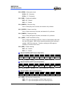
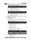
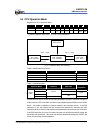
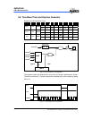
INTCR − INT Control Register ( Address : 0Bh )
Bit 7 Bit 6 Bit 5 Bit 4 Bit 3 Bit 2 Bit 1 Bit 0
INT1NR INT0EN 0 INT3ES1 INT3ES0 0 INT1ES TC2ES
Bit 7 ( INT1NR ) : INT1 noise reject time select
INT1NR = “0” : Pulses less than 63/fc are eliminated as noise
INT1NR = “1” : Pulses less than 15/fc are eliminated as noise
Bit 6 ( INT0EN ) : INT0 enable control
INT0EN = “0” : General I/O
INT0EN = “1” : /INT0 pin
Bit 5 : Reserved
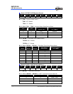
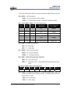
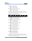
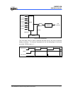
Bit 4 ~ Bit 3 ( INT3ES1 ~ INT3ES0) : INT3 edge select
INT3ES1 INT3ES0 Edge Select
0 0 Rising
0 1 Falling
1 0 Both edge
1 1 Reserved
Bit 2: Reserved
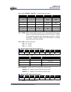
Bit 1 ( INT1ES ) : INT1 edge select
INT1ES = “0” : Rising edge
INT1ES = “1” : Falling edge
Bit 0 (TC2ES) : Timer/Counter 2 edge select.
TC2ES = “0” : Rising edge
TC2ES = “1” : Falling edge