


EM78P312N
8-Bit Microcontroller
Product Specification (V1.0) 10.03.2006
• 21
(This specification is subject to change without further notice)
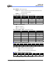
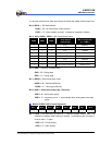
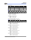
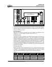
External Interrupt
INT Pin
Secondary
Function Pin
Enable Condition Edge
Digital Noise
Reject
/INT0 P60 ENI + INT0EN (IOCB) Falling -
INT1 P61 ENI + EXIE1 (IMR2) Rising or Falling 15/Fc, 63/Fc
INT3 P80, TC3 ENI + EXIE3 (IMR2)
Rising or Falling or
Rising/Falling
7/Fc
/INT5 P73, /SLEEP ENI + EXIE5 (IMR2) - -
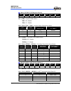
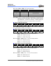
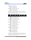
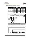
ADOSCR − AD Offset Control Register ( Address : 0Ch )
Bit 7 Bit 6 Bit 5 Bit 4 Bit 3 Bit 2 Bit 1 Bit 0
CALI SIGN VOF[2] VOF[1] VOF[0] 0 0 0
Bit 7 (CALI) : Calibration enable bit for A/D offset
CALI = “0” : disable Calibration
CALI = “1” : enable Calibration
Bit 6 ( SIGN ) : Offset voltage Polarity bit
SIGN = “0” : Negative voltage
SIGN = “1” : Positive voltage
Bit 5 ~ Bit 3 ( VOF[2] ~ VOF[0] ) : Offset voltage bits
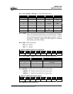
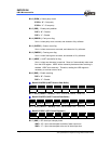
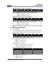
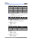
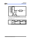
IMR1 − Interrupt Mask Register 1 ( Address : 0Eh )
Bit 7 Bit 6 Bit 5 Bit 4 Bit 3 Bit 2 Bit 1 Bit 0
EXIE5 TCIE2 ADIE 0 EXIE3 TCIE4 SPIE TCIE3
Bit 7 ( EXIE5 ) : External/INT5 pin Interrupt enable bit.
EXIE5 = “0” : disable EXIF5 interrupt
EXIE5 = “1” : enable EXIF5 interrupt
Bit 6 ( TCIE2 ) : Timer/Counter 2 Interrupt enable bit.
TCIE2 = “0” : disable TCIF2 interrupt
TCIE2 = “1” : enable TCIF2 interrupt
Bit 5 ( ADIE ) : ADC complete interrupt enable bit.
ADIE = “0” : disable ADIF interrupt
ADIE = “1” : enable ADIF interrupt
Bit 3 ( EXIE3 ) : External INT3 pin Interrupt enable bit.
EXIE3 = “0” : disable EXIF3 interrupt
EXIE3 = “1” : enable EXIF3 interrupt
Bit 2 ( TCIE4 ) : Timer/Counter 4 Interrupt enable bit.
TCIE4 = “0” : disable TCIF4 interrupt
TCIE4 = “1” : enable TCIF4 interrupt